How to Use FX2N PLC: Examples, Pinouts, and Specs
Introduction
The FX2N PLC (Programmable Logic Controller) is a compact and versatile automation device manufactured by Mitsubishi Clone. Designed for industrial control and automation applications, the FX2N-14MR model is part of the FX2N series, offering reliable performance, modular expandability, and support for multiple programming languages such as ladder logic. This PLC is ideal for small to medium-sized automation tasks, including machine control, process automation, and data acquisition.
Explore Projects Built with FX2N PLC


Explore Projects Built with FX2N PLC
Common Applications and Use Cases
- Industrial machinery control
- Conveyor belt automation
- Process monitoring and control
- Building automation systems
- Data logging and communication with SCADA systems
- Integration with sensors, actuators, and HMIs (Human-Machine Interfaces)
Technical Specifications
The FX2N-14MR is a compact PLC with built-in input and output capabilities, making it suitable for standalone or modular applications.
Key Technical Details
| Parameter | Specification |
|---|---|
| Manufacturer | Mitsubishi Clone |
| Model Number | FX2N-14MR |
| Power Supply Voltage | 24V DC or 100-240V AC (model-specific) |
| Digital Inputs | 8 |
| Digital Outputs | 6 (Relay type) |
| Programming Language | Ladder Logic, Instruction List, etc. |
| Communication Ports | RS-232, RS-485 (optional modules) |
| Memory Capacity | 8,000 steps |
| Expansion Capability | Yes (via additional I/O modules) |
| Operating Temperature | 0°C to 55°C |
| Dimensions | 90mm x 75mm x 60mm |
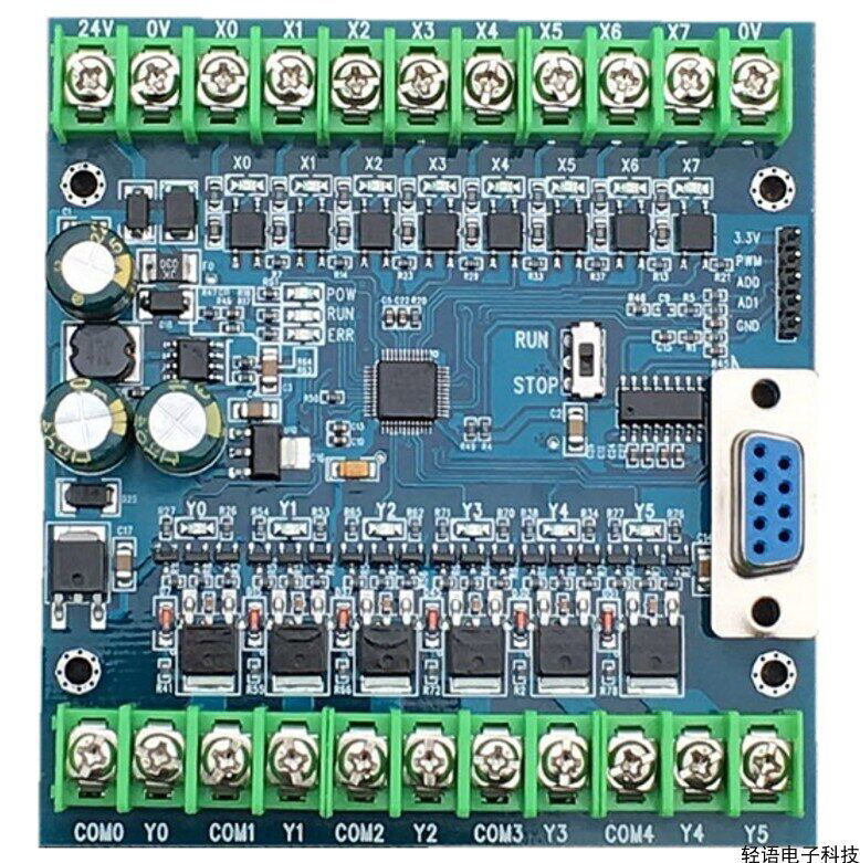
Pin Configuration and Descriptions
The FX2N-14MR features a terminal block for connecting inputs, outputs, and power. Below is the pin configuration:
Input Terminals
| Pin Number | Description | Signal Type |
|---|---|---|
| X0 | Input 0 | Digital Input |
| X1 | Input 1 | Digital Input |
| X2 | Input 2 | Digital Input |
| X3 | Input 3 | Digital Input |
| X4 | Input 4 | Digital Input |
| X5 | Input 5 | Digital Input |
| X6 | Input 6 | Digital Input |
| X7 | Input 7 | Digital Input |
Output Terminals
| Pin Number | Description | Signal Type |
|---|---|---|
| Y0 | Output 0 | Relay Output |
| Y1 | Output 1 | Relay Output |
| Y2 | Output 2 | Relay Output |
| Y3 | Output 3 | Relay Output |
| Y4 | Output 4 | Relay Output |
| Y5 | Output 5 | Relay Output |
Power Terminals
| Pin Number | Description |
|---|---|
| L/+ | Live/Positive Power |
| N/- | Neutral/Negative Power |
Usage Instructions
How to Use the FX2N PLC in a Circuit
- Power Connection: Connect the power supply to the L/+ and N/- terminals. Ensure the voltage matches the PLC's specifications (24V DC or 100-240V AC).
- Input Connections: Connect sensors or switches to the input terminals (X0-X7). Use pull-up or pull-down resistors if required.
- Output Connections: Connect actuators, relays, or other devices to the output terminals (Y0-Y5). Ensure the load does not exceed the output's current rating.
- Programming: Use Mitsubishi's GX Developer or GX Works software to write and upload ladder logic programs to the PLC via the communication port.
- Testing: After programming, test the PLC in a controlled environment to ensure proper operation.
Important Considerations and Best Practices
- Power Supply: Use a stable and regulated power supply to avoid damage to the PLC.
- Wiring: Ensure proper insulation and secure connections to prevent short circuits or signal interference.
- Grounding: Properly ground the PLC to reduce electrical noise and improve reliability.
- Expansion: When adding expansion modules, ensure compatibility with the FX2N series.
- Backup: Regularly back up the PLC program to avoid data loss during power failures or maintenance.
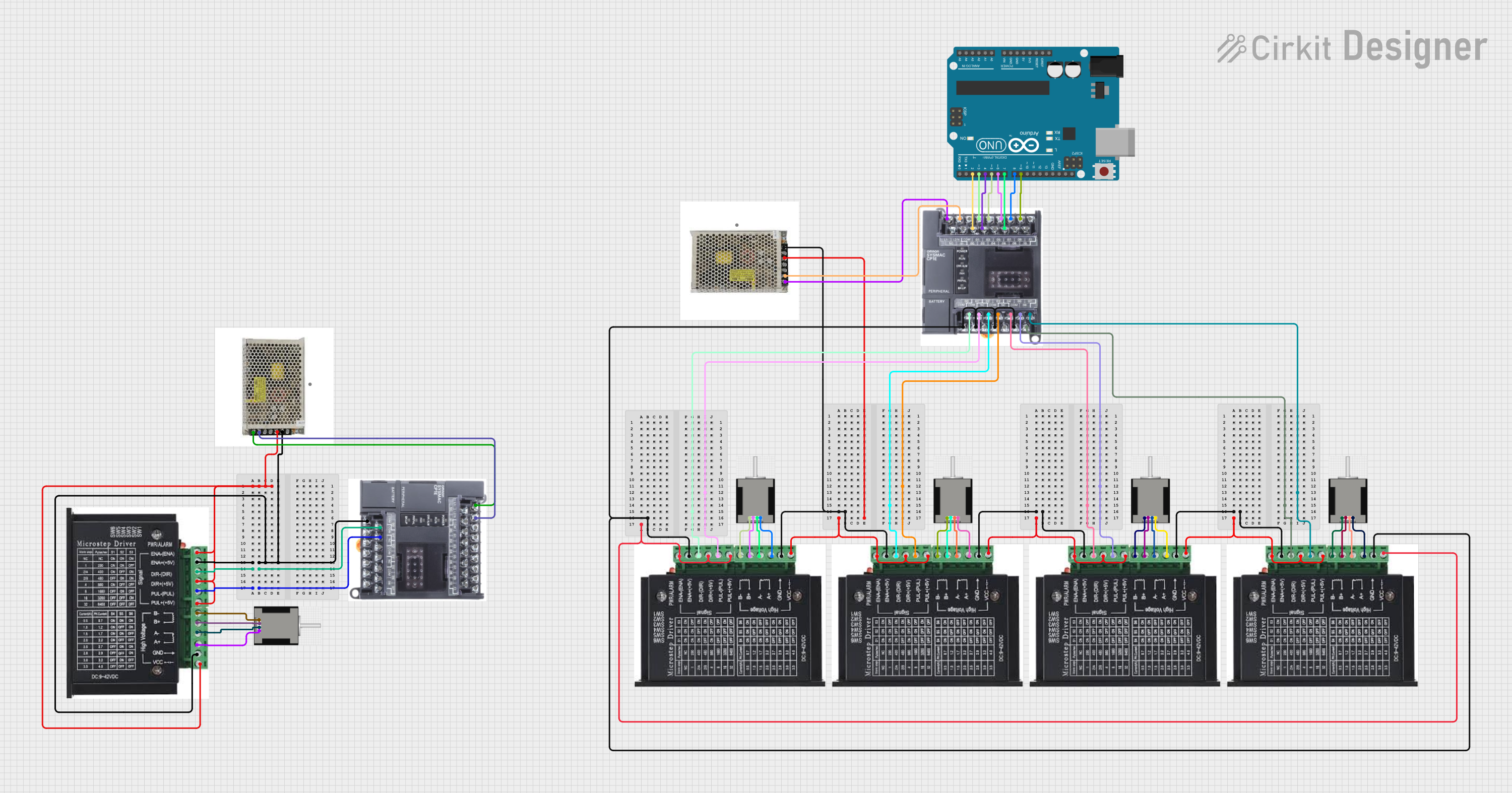
Example Code for Arduino UNO Integration
The FX2N PLC can communicate with an Arduino UNO via RS-232 or RS-485. Below is an example of Arduino code to send a signal to the PLC:
#include <SoftwareSerial.h>

// Define RX and TX pins for SoftwareSerial
SoftwareSerial plcSerial(10, 11); // RX = pin 10, TX = pin 11

void setup() {
  // Initialize serial communication
  Serial.begin(9600); // For debugging
  plcSerial.begin(9600); // Communication with FX2N PLC

  Serial.println("Arduino to FX2N PLC Communication Initialized");
}

void loop() {
  // Example: Send a signal to turn on Output Y0
  byte command[] = {0x02, 0x30, 0x30, 0x30, 0x31, 0x03};
  // Replace with actual command for your PLC

  plcSerial.write(command, sizeof(command)); // Send command to PLC
  Serial.println("Command sent to PLC");

  delay(1000); // Wait for 1 second
}
Note: The command format depends on the PLC's communication protocol. Refer to the FX2N communication manual for details.
Troubleshooting and FAQs
Common Issues and Solutions
PLC Not Powering On
- Cause: Incorrect power supply voltage or loose connections.
- Solution: Verify the power supply voltage and check all connections.
Inputs Not Responding
- Cause: Faulty wiring or incompatible sensors.
- Solution: Check sensor connections and ensure they are compatible with the PLC's input specifications.
Outputs Not Activating
- Cause: Overloaded output or incorrect wiring.
- Solution: Verify the load connected to the output and ensure it is within the rated capacity.
Communication Failure
- Cause: Incorrect baud rate or wiring issues.
- Solution: Ensure the baud rate matches the PLC settings and check the communication cable.
FAQs
Can the FX2N PLC be programmed without Mitsubishi software?
- Yes, third-party software may be used, but compatibility is not guaranteed.
What is the maximum expansion capacity of the FX2N-14MR?
- The FX2N series supports up to 256 I/O points with expansion modules.
Is the FX2N PLC compatible with SCADA systems?
- Yes, it can communicate with SCADA systems via RS-232 or RS-485 using appropriate protocols.
Can I use the FX2N PLC in outdoor environments?
- The PLC is designed for indoor use. If used outdoors, ensure it is housed in a weatherproof enclosure.