How to Use ESPS3-WROOM: Examples, Pinouts, and Specs
Introduction
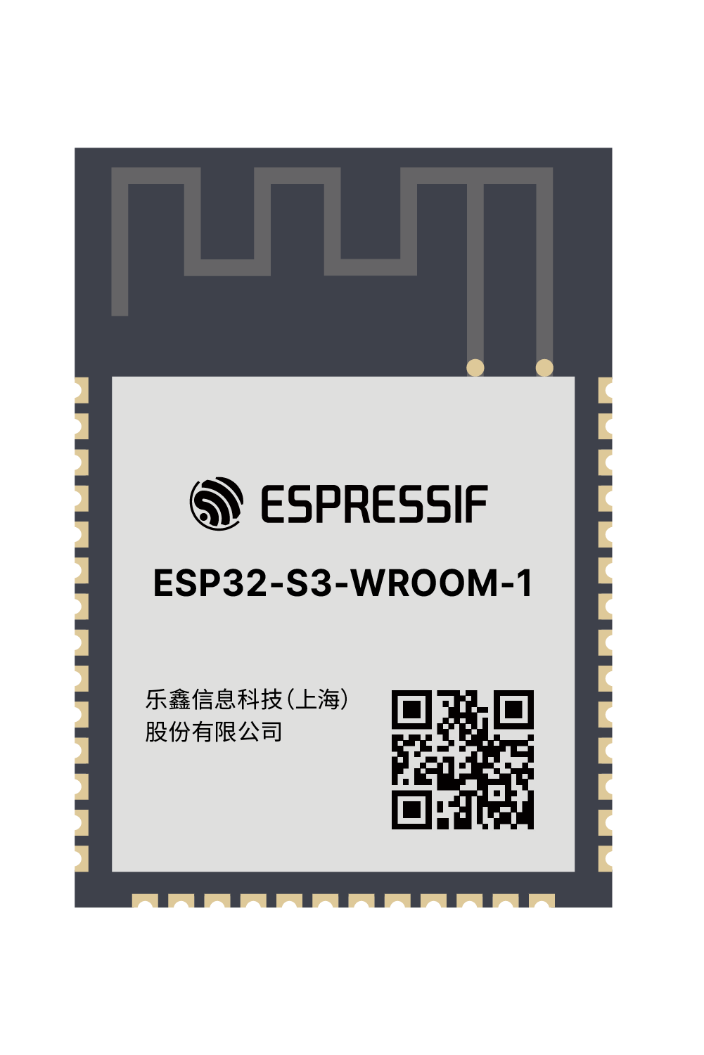
The ESPS3-WROOM, manufactured by Espressif, is a compact and versatile Wi-Fi and Bluetooth module designed for Internet of Things (IoT) applications. Based on the ESP32-S3 chip, this module offers high performance, low power consumption, and robust wireless communication capabilities. It is ideal for applications requiring reliable connectivity, such as smart home devices, industrial automation, wearable electronics, and more.
Explore Projects Built with ESPS3-WROOM

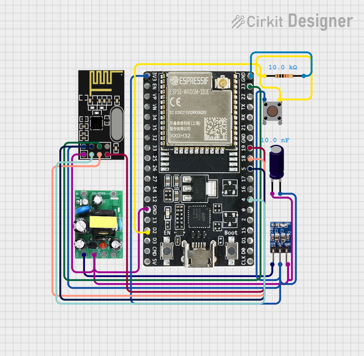


Explore Projects Built with ESPS3-WROOM
Common Applications and Use Cases
- Smart home devices (e.g., smart plugs, thermostats, and lighting systems)
- Industrial IoT (e.g., sensors, controllers, and monitoring systems)
- Wearable electronics
- Wireless data transmission and communication
- Prototyping and development of IoT solutions
Technical Specifications
Key Technical Details
| Parameter | Specification |
|---|---|
| Chipset | ESP32-S3 (Xtensa® 32-bit LX7 dual-core processor) |
| Wireless Connectivity | Wi-Fi 802.11 b/g/n (2.4 GHz), Bluetooth 5.0 LE |
| Flash Memory | 4 MB (default) |
| SRAM | 512 KB |
| Operating Voltage | 3.0V to 3.6V |
| Power Consumption | Ultra-low power consumption in deep sleep mode (as low as 10 µA) |
| GPIO Pins | Up to 45 GPIOs (depending on configuration) |
| Interfaces | SPI, I2C, I2S, UART, PWM, ADC, DAC, USB OTG |
| Operating Temperature | -40°C to +85°C |
| Dimensions | 18 mm x 25.5 mm x 2.4 mm |
| Certifications | FCC, CE, IC, SRRC, and more |
Pin Configuration and Descriptions
The ESPS3-WROOM module has multiple pins for various functionalities. Below is a table summarizing the key pins and their descriptions:
| Pin Number | Pin Name | Functionality |
|---|---|---|
| 1 | GND | Ground |
| 2 | 3V3 | Power supply input (3.3V) |
| 3 | EN | Enable pin (active high) |
| 4 | IO0 | GPIO0, used for boot mode selection |
| 5 | IO1 | GPIO1, general-purpose input/output |
| 6 | TXD0 | UART0 transmit data |
| 7 | RXD0 | UART0 receive data |
| 8 | IO2 | GPIO2, supports PWM, ADC, and other functions |
| 9 | IO3 | GPIO3, general-purpose input/output |
| 10 | IO4 | GPIO4, supports SPI and other functions |
| 11 | IO5 | GPIO5, general-purpose input/output |
| 12 | IO12 | GPIO12, supports ADC and other functions |
| 13 | IO13 | GPIO13, supports I2C and other functions |
| 14 | IO14 | GPIO14, supports SPI and other functions |
| 15 | IO15 | GPIO15, general-purpose input/output |
Note: The exact pinout may vary depending on the specific module variant. Refer to the official datasheet for detailed pin mappings.
Usage Instructions
How to Use the ESPS3-WROOM in a Circuit
- Power Supply: Connect the 3V3 pin to a stable 3.3V power source and the GND pin to ground.
- Boot Mode Selection: Use GPIO0 (IO0) to select the boot mode. Pull it low during power-up to enter programming mode.
- Communication: Use the UART pins (TXD0 and RXD0) for serial communication with a microcontroller or computer.
- GPIO Usage: Configure the GPIO pins as needed for your application (e.g., input, output, PWM, ADC).
- Antenna: Ensure the onboard antenna has sufficient clearance from metallic objects to avoid signal interference.
Important Considerations and Best Practices
- Power Supply: Use a low-noise, stable 3.3V power source to ensure reliable operation.
- Programming: Use a USB-to-UART adapter to program the module via the UART interface.
- Antenna Placement: Avoid placing the module near metal surfaces or enclosures that could block the wireless signal.
- Deep Sleep Mode: Utilize the deep sleep mode to minimize power consumption in battery-powered applications.
- Firmware Updates: Regularly update the firmware to benefit from the latest features and security patches.
Example: Connecting to an Arduino UNO
Below is an example of how to connect the ESPS3-WROOM to an Arduino UNO and send data over Wi-Fi:
Wiring Diagram
| ESPS3-WROOM Pin | Arduino UNO Pin |
|---|---|
| 3V3 | 3.3V |
| GND | GND |
| TXD0 | RX (Pin 0) |
| RXD0 | TX (Pin 1) |
| EN | 3.3V (via 10kΩ pull-up resistor) |
Example Code
#include <WiFi.h> // Include the Wi-Fi library for ESP32-S3

// Replace with your network credentials
const char* ssid = "Your_SSID";
const char* password = "Your_PASSWORD";

void setup() {
  Serial.begin(115200); // Initialize serial communication
  delay(1000);

  // Connect to Wi-Fi
  Serial.println("Connecting to Wi-Fi...");
  WiFi.begin(ssid, password);

  while (WiFi.status() != WL_CONNECTED) {
    delay(500);
    Serial.print(".");
  }

  Serial.println("\nWi-Fi connected!");
  Serial.print("IP Address: ");
  Serial.println(WiFi.localIP()); // Print the module's IP address
}

void loop() {
  // Add your main code here
}
Note: Ensure the Arduino UNO's RX and TX pins are connected correctly to avoid communication issues.
Troubleshooting and FAQs
Common Issues and Solutions
Module Not Powering On
- Cause: Insufficient or unstable power supply.
- Solution: Ensure the power source provides a stable 3.3V and sufficient current.
Wi-Fi Connection Fails
- Cause: Incorrect SSID or password.
- Solution: Double-check the network credentials in your code.
Serial Communication Not Working
- Cause: Incorrect wiring or baud rate mismatch.
- Solution: Verify the TX and RX connections and ensure the baud rate matches in the code.
Module Not Entering Programming Mode
- Cause: GPIO0 not pulled low during power-up.
- Solution: Check the GPIO0 connection and ensure it is pulled low when resetting the module.
FAQs
Q: Can the ESPS3-WROOM operate on 5V?
- A: No, the module requires a 3.3V power supply. Using 5V may damage the module.
Q: How do I update the firmware?
- A: Use the Espressif ESP-IDF or a compatible flashing tool to upload the latest firmware via the UART interface.
Q: Can I use the ESPS3-WROOM for Bluetooth communication?
- A: Yes, the module supports Bluetooth 5.0 LE for low-energy communication.
Q: What is the maximum Wi-Fi range?
- A: The range depends on the environment but typically extends up to 100 meters in open spaces.
By following this documentation, you can effectively integrate the ESPS3-WROOM module into your IoT projects and take full advantage of its capabilities.