Cirkit Designer Logo
Cirkit Designer
Your all-in-one circuit design IDE
Home / 
Component Documentation

How to Use IRF520 Module: Examples, Pinouts, and Specs

Image of IRF520 Module
Cirkit Designer LogoDesign with IRF520 Module in Cirkit Designer

Introduction

The IRF520 Module is a power MOSFET driver designed for switching applications. It is capable of controlling high voltage and high current loads, making it an essential component for various electronic projects. The module is widely used in applications such as motor control, LED dimming, and other high-power switching tasks. It features a built-in gate resistor and protection diodes, which enhance its performance and reliability.

Common applications of the IRF520 Module include:

  • Driving DC motors in robotics and automation systems
  • Controlling high-power LEDs for dimming or lighting systems
  • Switching high-current loads in power management circuits
  • General-purpose switching in hobbyist and industrial projects

Explore Projects Built with IRF520 Module

Use Cirkit Designer to design, explore, and prototype these projects online. Some projects support real-time simulation. Click "Open Project" to start designing instantly!
STM32F103C8T6-Based Access Control System with RFID and Servo Motor Actuation
Image of PARCEL SORTING SEM 5: A project utilizing IRF520 Module in a practical application
This circuit features an STM32F103C8T6 microcontroller interfaced with an RFID-RC522 module for RFID reading, two servo motors, an IR sensor, and a 2-channel relay module controlling two hobby motors. The microcontroller manages the communication with the RFID module via SPI (MOSI, MISO, SCK, SDA), processes the IR sensor signal, and outputs PWM signals to the servo motors. The relay module is used to switch the hobby motors on and off, with the microcontroller providing control signals and power supplies providing the necessary voltage levels for the different components.
Cirkit Designer LogoOpen Project in Cirkit Designer
Arduino Mega 2560 Controlled 12V LED Strip with Potentiometer and IRF520 PWM
Image of Backlight: A project utilizing IRF520 Module in a practical application
This circuit uses an Arduino Mega 2560 to control the brightness of a 12V white LED strip via a potentiometer and an IRF520 PWM module. The potentiometer adjusts the input signal to the Arduino, which then modulates the LED strip's brightness through the IRF520 PWM module, powered by a 12V power supply.
Cirkit Designer LogoOpen Project in Cirkit Designer
Arduino UNO-Based Smart Fan Controller with Temperature and Humidity Sensing
Image of 123: A project utilizing IRF520 Module in a practical application
This circuit uses an Arduino UNO to control a 12V fan and two LEDs (red and blue) based on input from a DHT11 humidity and temperature sensor. The IRF520 PWM module is used to drive the fan, and the LEDs are connected through resistors to the Arduino's digital pins for status indication.
Cirkit Designer LogoOpen Project in Cirkit Designer
Arduino Mega 2560 Based Security System with Fingerprint Authentication and SMS Alerts
Image of Door security system: A project utilizing IRF520 Module in a practical application
This circuit features an Arduino Mega 2560 microcontroller interfaced with a SIM800L GSM module, two fingerprint scanners, an I2C LCD display, an IR sensor, and a piezo buzzer. Power management is handled by a PowerBoost 1000 Basic Pad USB, a TP4056 charging module, and a Li-ion 18650 battery, with an option to use a Mini AC-DC 110V-230V to 5V 700mA module for direct power supply. The primary functionality appears to be a security system with GSM communication capabilities, biometric access control, and visual/audible feedback.
Cirkit Designer LogoOpen Project in Cirkit Designer

Explore Projects Built with IRF520 Module

Use Cirkit Designer to design, explore, and prototype these projects online. Some projects support real-time simulation. Click "Open Project" to start designing instantly!
Image of PARCEL SORTING SEM 5: A project utilizing IRF520 Module in a practical application
STM32F103C8T6-Based Access Control System with RFID and Servo Motor Actuation
This circuit features an STM32F103C8T6 microcontroller interfaced with an RFID-RC522 module for RFID reading, two servo motors, an IR sensor, and a 2-channel relay module controlling two hobby motors. The microcontroller manages the communication with the RFID module via SPI (MOSI, MISO, SCK, SDA), processes the IR sensor signal, and outputs PWM signals to the servo motors. The relay module is used to switch the hobby motors on and off, with the microcontroller providing control signals and power supplies providing the necessary voltage levels for the different components.
Cirkit Designer LogoOpen Project in Cirkit Designer
Image of Backlight: A project utilizing IRF520 Module in a practical application
Arduino Mega 2560 Controlled 12V LED Strip with Potentiometer and IRF520 PWM
This circuit uses an Arduino Mega 2560 to control the brightness of a 12V white LED strip via a potentiometer and an IRF520 PWM module. The potentiometer adjusts the input signal to the Arduino, which then modulates the LED strip's brightness through the IRF520 PWM module, powered by a 12V power supply.
Cirkit Designer LogoOpen Project in Cirkit Designer
Image of 123: A project utilizing IRF520 Module in a practical application
Arduino UNO-Based Smart Fan Controller with Temperature and Humidity Sensing
This circuit uses an Arduino UNO to control a 12V fan and two LEDs (red and blue) based on input from a DHT11 humidity and temperature sensor. The IRF520 PWM module is used to drive the fan, and the LEDs are connected through resistors to the Arduino's digital pins for status indication.
Cirkit Designer LogoOpen Project in Cirkit Designer
Image of Door security system: A project utilizing IRF520 Module in a practical application
Arduino Mega 2560 Based Security System with Fingerprint Authentication and SMS Alerts
This circuit features an Arduino Mega 2560 microcontroller interfaced with a SIM800L GSM module, two fingerprint scanners, an I2C LCD display, an IR sensor, and a piezo buzzer. Power management is handled by a PowerBoost 1000 Basic Pad USB, a TP4056 charging module, and a Li-ion 18650 battery, with an option to use a Mini AC-DC 110V-230V to 5V 700mA module for direct power supply. The primary functionality appears to be a security system with GSM communication capabilities, biometric access control, and visual/audible feedback.
Cirkit Designer LogoOpen Project in Cirkit Designer

Technical Specifications

Below are the key technical details of the IRF520 Module:

Parameter Value
Operating Voltage 3.3V to 5V (logic level input)
Maximum Drain-Source Voltage (VDS) 100V
Maximum Drain Current (ID) 9.2A
Gate Threshold Voltage (VGS(th)) 2.0V to 4.0V
On-Resistance (RDS(on)) 0.27Ω (at VGS = 10V)
Power Dissipation 40W
Module Dimensions ~33mm x 25mm x 15mm

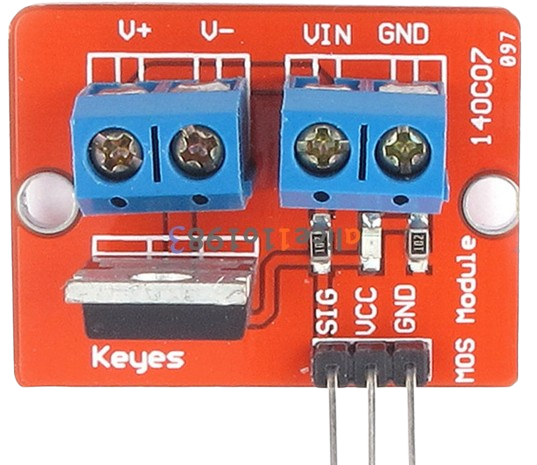
Pin Configuration and Descriptions

The IRF520 Module typically has a 3-pin input interface and a 2-pin output interface. Below is the pin configuration:

Input Pins

Pin Name Description
1 VCC Connect to the logic-level voltage (3.3V or 5V).
2 GND Ground connection for the module.
3 Signal Control signal input to switch the MOSFET on or off.

Output Pins

Pin Name Description
1 Drain Connect to the positive terminal of the load.
2 Source Connect to the negative terminal of the load or GND.

Usage Instructions

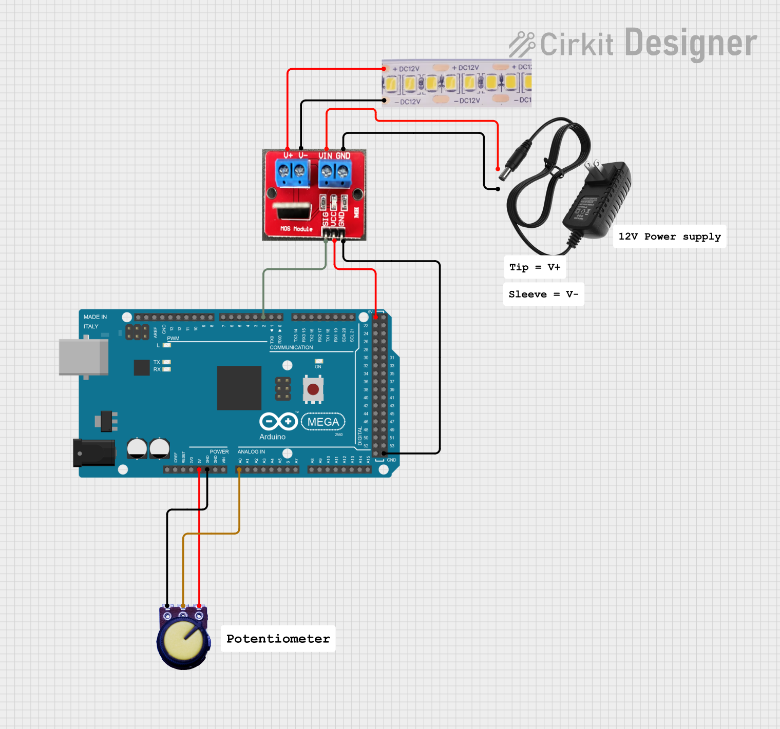
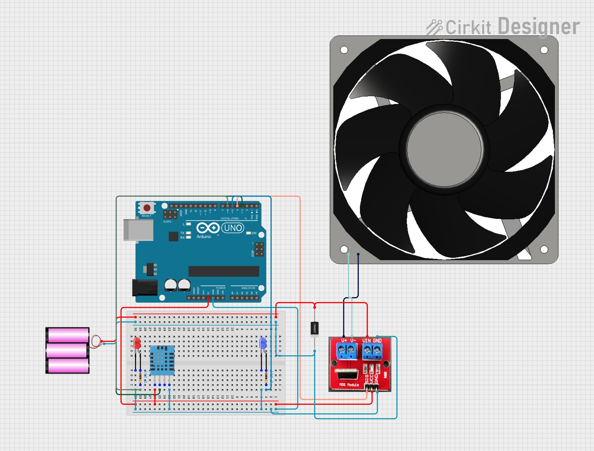
How to Use the IRF520 Module in a Circuit

  1. Power the Module: Connect the VCC pin to a 3.3V or 5V logic-level power source and the GND pin to the ground of your circuit.
  2. Connect the Load: Attach the positive terminal of your load (e.g., motor or LED) to the Drain pin and the negative terminal to the Source pin or ground.
  3. Control the Module: Use a microcontroller (e.g., Arduino UNO) or other logic-level device to send a control signal to the Signal pin. A HIGH signal will turn the MOSFET on, allowing current to flow through the load, while a LOW signal will turn it off.

Important Considerations and Best Practices

  • Ensure the load does not exceed the maximum current rating of 9.2A.
  • Use a heat sink if the module is expected to handle high power for extended periods.
  • Avoid exceeding the maximum drain-source voltage of 100V to prevent damage.
  • For inductive loads (e.g., motors), consider adding a flyback diode across the load to protect the MOSFET from voltage spikes.

Example: Using the IRF520 Module with an Arduino UNO

Below is an example of how to use the IRF520 Module to control an LED with an Arduino UNO:

// Define the pin connected to the IRF520 Signal pin
const int mosfetPin = 9;

void setup() {
  pinMode(mosfetPin, OUTPUT); // Set the MOSFET pin as an output
}

void loop() {
  digitalWrite(mosfetPin, HIGH); // Turn the MOSFET on (LED ON)
  delay(1000);                  // Wait for 1 second
  digitalWrite(mosfetPin, LOW);  // Turn the MOSFET off (LED OFF)
  delay(1000);                  // Wait for 1 second
}

Note: Ensure the Arduino GND is connected to the IRF520 Module GND for proper operation.

Troubleshooting and FAQs

Common Issues and Solutions

  1. The load does not turn on:

    • Verify that the control signal is reaching the Signal pin.
    • Ensure the VCC and GND connections are secure.
    • Check if the load is within the module's voltage and current limits.
  2. The MOSFET overheats:

    • Use a heat sink to dissipate heat during high-power operation.
    • Ensure the load current does not exceed 9.2A.
  3. The module does not respond to the control signal:

    • Confirm that the control signal voltage is within the acceptable range (3.3V to 5V).
    • Check for loose or incorrect wiring.
  4. Voltage spikes damage the MOSFET:

    • For inductive loads, add a flyback diode across the load to suppress voltage spikes.

FAQs

Q: Can the IRF520 Module be used with a 12V load?
A: Yes, the module can handle loads up to 100V, so a 12V load is well within its operating range. Ensure the current does not exceed 9.2A.

Q: Is the IRF520 Module compatible with 3.3V logic devices?
A: Yes, the module can be controlled with 3.3V logic signals, but performance may vary depending on the load. For optimal performance, use a 5V control signal.

Q: Do I need additional components to use the IRF520 Module?
A: The module includes a built-in gate resistor and protection diodes, so no additional components are required for basic operation. However, a flyback diode is recommended for inductive loads.