How to Use Heart Rate & Oximeter Sensor V2.0: Examples, Pinouts, and Specs
Introduction
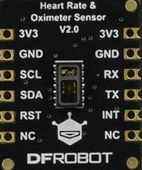
The Heart Rate & Oximeter Sensor V2.0 (Manufacturer Part ID: MAX30102) by DFROBOT is a compact and highly integrated sensor module designed for measuring heart rate and blood oxygen saturation (SpO2) levels. It utilizes photoplethysmography (PPG) technology, which detects changes in blood volume through light absorption. This sensor is widely used in health monitoring devices, fitness trackers, and medical applications.
Explore Projects Built with Heart Rate & Oximeter Sensor V2.0
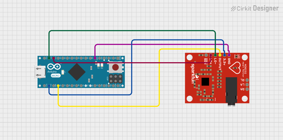
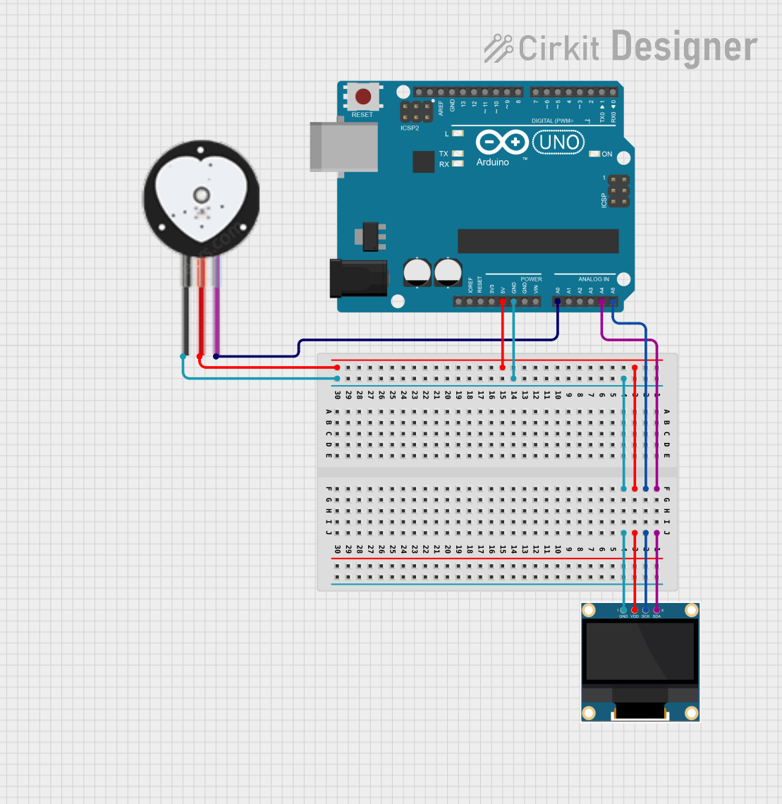
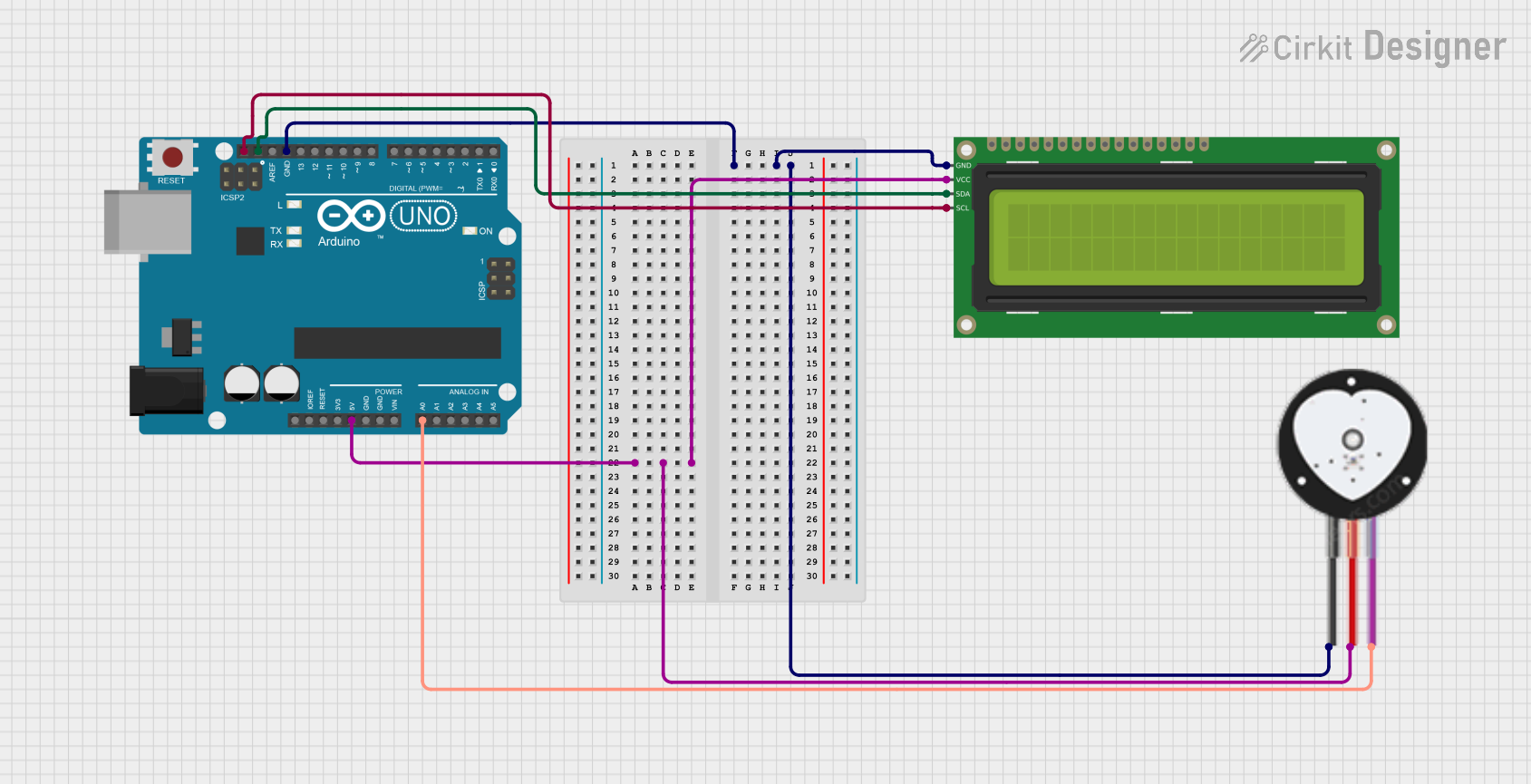
Explore Projects Built with Heart Rate & Oximeter Sensor V2.0
Common Applications
- Wearable health monitoring devices
- Fitness trackers
- Medical diagnostic tools
- Research and development in biomedical engineering
- IoT-based health monitoring systems
Technical Specifications
The following table outlines the key technical details of the MAX30102 sensor module:
| Parameter | Value |
|---|---|
| Operating Voltage | 1.8V (internal) / 3.3V (I/O voltage) |
| Operating Current | 600 µA (typical) |
| Standby Current | 0.7 µA |
| Measurement Method | Photoplethysmography (PPG) |
| Communication Interface | I2C |
| I2C Address | 0x57 (default) |
| Wavelengths | Red: 660 nm, Infrared: 880 nm |
| Sampling Rate | Programmable (50 Hz to 400 Hz) |
| Operating Temperature | -40°C to +85°C |
| Dimensions | 13.0 mm x 8.0 mm x 1.2 mm |
Pin Configuration
The MAX30102 module has the following pinout:
| Pin | Name | Description |
|---|---|---|
| 1 | VIN | Power supply input (3.3V) |
| 2 | GND | Ground |
| 3 | SDA | I2C data line |
| 4 | SCL | I2C clock line |
| 5 | INT | Interrupt output (active low) |
Usage Instructions
Connecting the Sensor
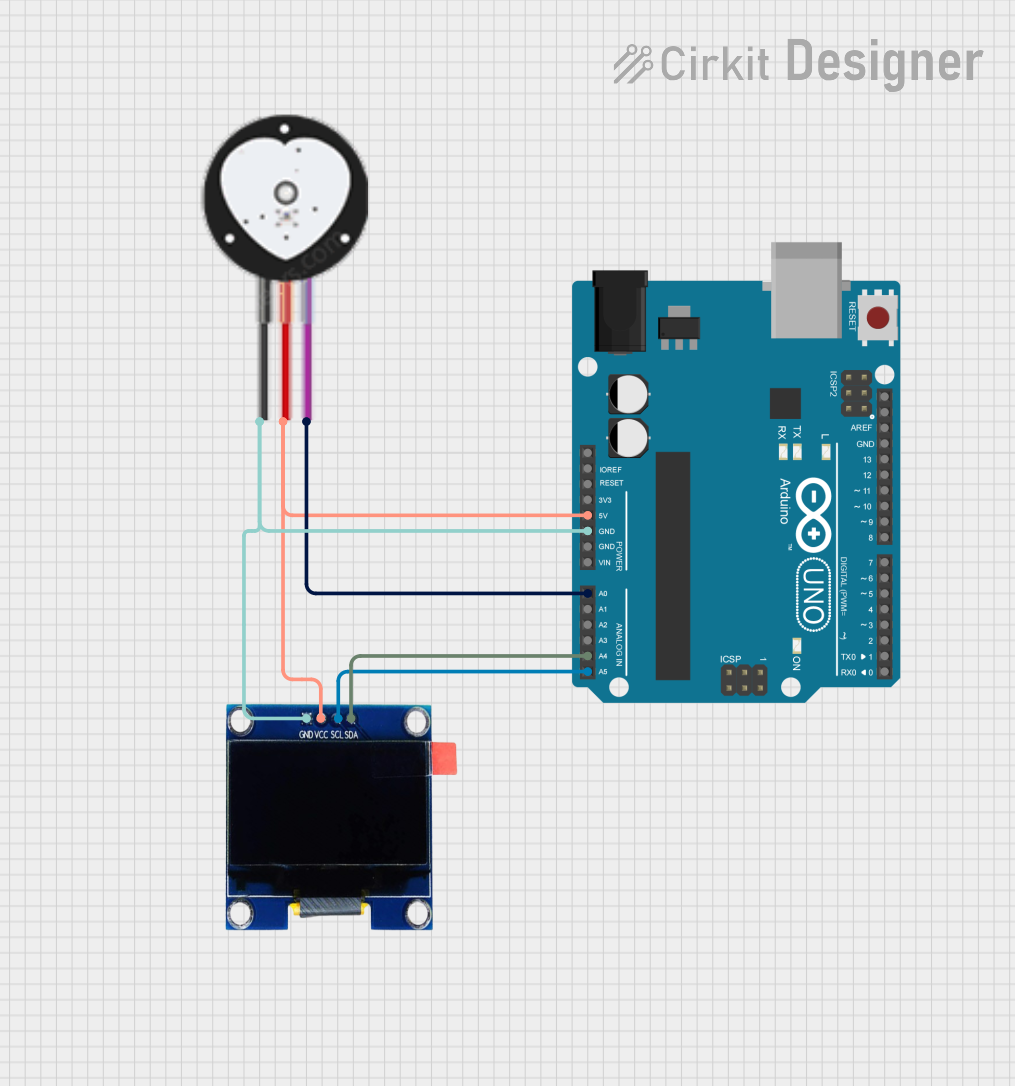
To use the MAX30102 sensor with a microcontroller (e.g., Arduino UNO), follow these steps:
- Power Supply: Connect the
VINpin to the 3.3V output of the microcontroller and theGNDpin to ground. - I2C Communication: Connect the
SDApin to the Arduino'sA4pin and theSCLpin to theA5pin (for Arduino UNO). Use pull-up resistors (typically 4.7 kΩ) on theSDAandSCLlines if not already included on the module. - Interrupt Pin: The
INTpin can be connected to a digital input pin on the microcontroller if interrupt-based data reading is required.
Sample Code for Arduino UNO
Below is an example Arduino sketch to read heart rate and SpO2 data from the MAX30102 sensor using the DFRobot MAX30102 library:
#include <Wire.h>
#include "DFRobot_MAX30102.h"

// Create an instance of the MAX30102 sensor
DFRobot_MAX30102 max30102;

void setup() {
  Serial.begin(9600); // Initialize serial communication
  Wire.begin();       // Initialize I2C communication

  // Initialize the MAX30102 sensor
  if (!max30102.begin()) {
    Serial.println("MAX30102 initialization failed. Check connections.");
    while (1); // Halt execution if initialization fails
  }
  Serial.println("MAX30102 initialized successfully.");
}

void loop() {
  // Variables to store heart rate and SpO2 values
  uint8_t heartRate = 0;
  uint8_t spo2 = 0;

  // Read heart rate and SpO2 data
  if (max30102.read(&heartRate, &spo2)) {
    Serial.print("Heart Rate: ");
    Serial.print(heartRate);
    Serial.print(" bpm, SpO2: ");
    Serial.print(spo2);
    Serial.println(" %");
  } else {
    Serial.println("Failed to read data. Ensure proper sensor placement.");
  }

  delay(1000); // Wait 1 second before the next reading
}
Important Considerations
- Ensure the sensor is securely connected to the microcontroller to avoid communication errors.
- Avoid exposing the sensor to direct sunlight or strong ambient light, as this may interfere with measurements.
- For accurate readings, ensure the sensor is in close contact with the skin (e.g., fingertip or earlobe).
- Use a stable power supply to minimize noise in the measurements.
Troubleshooting and FAQs
Common Issues and Solutions
Sensor Not Detected
- Cause: Incorrect I2C wiring or address mismatch.
- Solution: Verify the
SDAandSCLconnections. Ensure the I2C address is set to0x57in the code.
Inaccurate Readings
- Cause: Poor sensor placement or excessive ambient light.
- Solution: Ensure the sensor is in close contact with the skin and shield it from ambient light.
Initialization Fails
- Cause: Power supply issues or damaged sensor.
- Solution: Check the
VINandGNDconnections. Ensure the power supply is 3.3V.
Data Read Errors
- Cause: Noise or unstable I2C communication.
- Solution: Use pull-up resistors on the
SDAandSCLlines if not already present.
FAQs
Q1: Can the MAX30102 be powered with 5V?
A1: No, the MAX30102 operates at 3.3V. Using 5V may damage the sensor.
Q2: What is the maximum sampling rate of the sensor?
A2: The MAX30102 supports a programmable sampling rate of up to 400 Hz.
Q3: Can this sensor be used for continuous monitoring?
A3: Yes, the MAX30102 is designed for continuous monitoring applications, but ensure proper heat dissipation to avoid overheating.
Q4: Is the sensor compatible with other microcontrollers?
A4: Yes, the MAX30102 can be used with any microcontroller that supports I2C communication, such as ESP32, Raspberry Pi, etc.
By following this documentation, users can effectively integrate the Heart Rate & Oximeter Sensor V2.0 into their projects for reliable health monitoring.