How to Use NFC/RFID reader PN532: Examples, Pinouts, and Specs
Introduction
The PN532 v.3, manufactured by Arduino, is a versatile NFC (Near Field Communication) and RFID (Radio Frequency Identification) reader/writer module. It is designed to enable seamless communication with NFC-enabled devices and RFID tags. The module supports multiple modes of operation, including card emulation, peer-to-peer communication, and reader mode. This makes it an excellent choice for a wide range of applications, such as:
- Contactless payment systems
- Access control and security systems
- Data exchange between devices
- Inventory management and tracking
- Smart posters and interactive kiosks
The PN532 is widely used due to its compatibility with various communication protocols and ease of integration with microcontrollers like the Arduino UNO.
Explore Projects Built with NFC/RFID reader PN532


Explore Projects Built with NFC/RFID reader PN532
Technical Specifications
Below are the key technical details and pin configuration for the PN532 v.3 module:
Key Technical Details
| Parameter | Specification |
|---|---|
| Operating Voltage | 3.3V to 5V |
| Communication Interfaces | I2C, SPI, UART |
| Operating Frequency | 13.56 MHz |
| Supported Protocols | ISO/IEC 14443A/B, FeliCa, NFC Forum |
| Maximum Communication Range | Up to 5 cm (depending on antenna size) |
| Current Consumption | ~50 mA (active mode) |
| Dimensions | 40 mm x 40 mm |
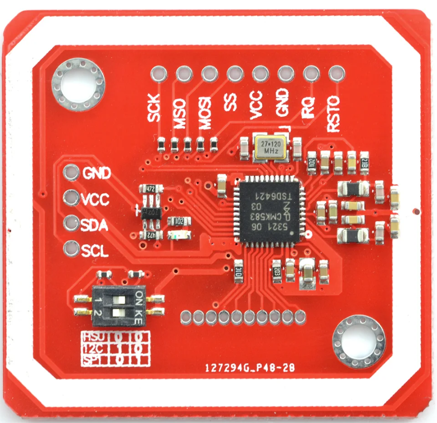
Pin Configuration and Descriptions
| Pin Name | Pin Number | Description |
|---|---|---|
| VCC | 1 | Power supply input (3.3V or 5V) |
| GND | 2 | Ground |
| SDA | 3 | I2C data line |
| SCL | 4 | I2C clock line |
| MOSI | 5 | SPI Master Out Slave In |
| MISO | 6 | SPI Master In Slave Out |
| SCK | 7 | SPI clock line |
| SS | 8 | SPI slave select |
| RX | 9 | UART receive |
| TX | 10 | UART transmit |
| IRQ | 11 | Interrupt request output |
| RST | 12 | Reset pin |
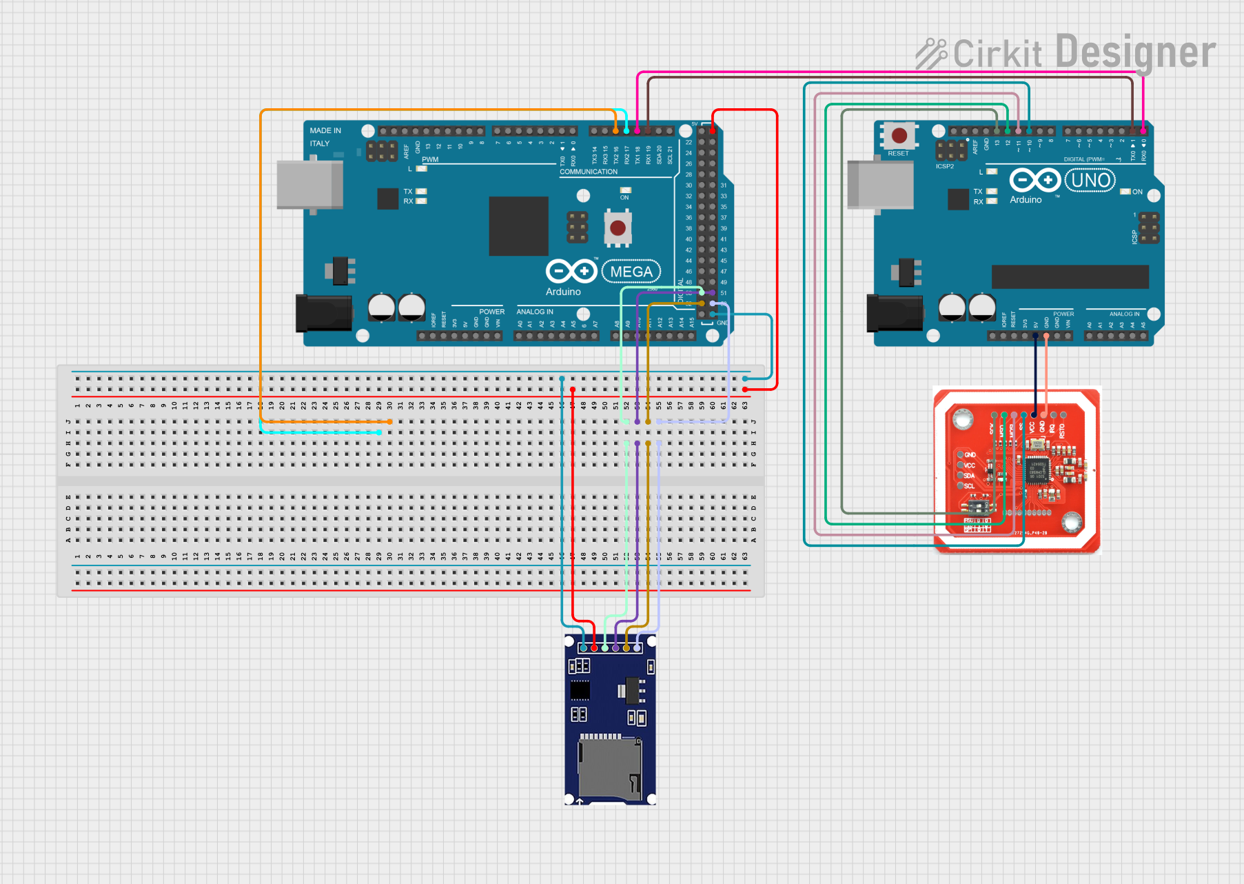
Usage Instructions
How to Use the PN532 in a Circuit
- Power the Module: Connect the VCC pin to a 3.3V or 5V power source and the GND pin to ground.
- Select Communication Interface: The PN532 supports I2C, SPI, and UART. Use the appropriate pins based on your chosen interface:
- For I2C: Connect SDA and SCL to the corresponding pins on your microcontroller.
- For SPI: Connect MOSI, MISO, SCK, and SS to the respective SPI pins on your microcontroller.
- For UART: Connect RX and TX to the UART pins on your microcontroller.
- Install Required Libraries: If using an Arduino, install the "Adafruit_PN532" library from the Arduino Library Manager.
- Write and Upload Code: Use the example code provided below to test the module.
Example Code for Arduino UNO (I2C Communication)
#include <Wire.h>
#include <Adafruit_PN532.h>

// Define the I2C pins for the PN532
#define SDA_PIN 2  // Connect to SDA on PN532
#define SCL_PIN 3  // Connect to SCL on PN532

// Create an instance of the Adafruit_PN532 class
Adafruit_PN532 nfc(SDA_PIN, SCL_PIN);

void setup() {
  Serial.begin(9600); // Initialize serial communication
  Serial.println("Initializing PN532...");

  nfc.begin(); // Initialize the PN532 module

  // Check if the PN532 is detected
  uint32_t versiondata = nfc.getFirmwareVersion();
  if (!versiondata) {
    Serial.println("Didn't find PN532 module!");
    while (1); // Halt execution if module is not found
  }

  // Display firmware version
  Serial.print("Found PN532 with firmware version: ");
  Serial.println((versiondata >> 16) & 0xFF, HEX);

  // Configure the module to read RFID tags
  nfc.SAMConfig();
  Serial.println("Waiting for an NFC card...");
}

void loop() {
  uint8_t success;
  uint8_t uid[] = { 0 }; // Buffer to store the UID
  uint8_t uidLength;     // Length of the UID

  // Attempt to read an NFC card
  success = nfc.readPassiveTargetID(PN532_MIFARE_ISO14443A, uid, &uidLength);

  if (success) {
    Serial.println("NFC card detected!");
    Serial.print("UID Length: "); Serial.print(uidLength, DEC); Serial.println(" bytes");
    Serial.print("UID Value: ");
    for (uint8_t i = 0; i < uidLength; i++) {
      Serial.print(" 0x"); Serial.print(uid[i], HEX);
    }
    Serial.println();
    delay(1000); // Wait before scanning again
  }
}
Important Considerations and Best Practices
- Ensure the module is powered with the correct voltage (3.3V or 5V) to avoid damage.
- Keep the antenna area clear of obstructions for optimal communication range.
- Use proper pull-up resistors for I2C communication if not already included on the module.
- Avoid placing the module near metal objects, as they can interfere with NFC/RFID signals.
Troubleshooting and FAQs
Common Issues and Solutions
Module Not Detected:
- Ensure the wiring is correct and matches the selected communication interface.
- Verify that the power supply voltage is within the specified range.
- Check if the required library (e.g., Adafruit_PN532) is installed and included in your code.
Short Communication Range:
- Ensure there are no obstructions near the antenna.
- Verify that the RFID tag or NFC device is within the specified range (up to 5 cm).
Interference with Other Devices:
- Avoid placing the PN532 near other electronic devices that operate at 13.56 MHz.
- Use proper shielding if interference persists.
Error Reading Tags:
- Confirm that the tag is compatible with the supported protocols (e.g., ISO/IEC 14443A/B).
- Ensure the tag is not damaged or corrupted.
FAQs
Q: Can the PN532 read multiple tags simultaneously?
A: No, the PN532 can only read one tag at a time. Attempting to read multiple tags may result in errors.
Q: Is the PN532 compatible with smartphones?
A: Yes, the PN532 can communicate with NFC-enabled smartphones in peer-to-peer mode or read mode.
Q: Can I use the PN532 with a 5V microcontroller?
A: Yes, the PN532 is compatible with both 3.3V and 5V systems, but ensure proper wiring and voltage levels.
Q: How do I increase the communication range?
A: The range is primarily determined by the antenna size and design. Using a larger or optimized antenna may improve range.