How to Use VKDI20370 ESC Regulator: Examples, Pinouts, and Specs
Introduction
The VKDI20370 is an Electronic Speed Controller (ESC) manufactured by Chinases. It is specifically designed for controlling the speed of brushless motors in remote-controlled (RC) vehicles, drones, and other applications requiring precise motor control. This ESC regulates the power supplied to the motor based on input signals from a receiver, ensuring smooth acceleration, deceleration, and efficient operation.
Explore Projects Built with VKDI20370 ESC Regulator


Explore Projects Built with VKDI20370 ESC Regulator
Common Applications
- RC cars, boats, and airplanes
- Drones and quadcopters
- Robotics and automation systems
- Electric-powered model vehicles
The VKDI20370 is ideal for hobbyists and professionals seeking reliable and efficient motor control in their projects.
Technical Specifications
Key Specifications
| Parameter | Value |
|---|---|
| Manufacturer | Chinases |
| Part ID | VKDI20370 |
| Input Voltage Range | 6V - 20V |
| Continuous Current | 30A |
| Peak Current | 37A (for 10 seconds) |
| Supported Motor Types | Brushless DC (BLDC) motors |
| Signal Input Type | PWM (Pulse Width Modulation) |
| PWM Signal Range | 1ms - 2ms (standard RC signal) |
| Operating Temperature | -10°C to 60°C |
| Dimensions | 45mm x 25mm x 10mm |
| Weight | 25g |
Pin Configuration and Descriptions
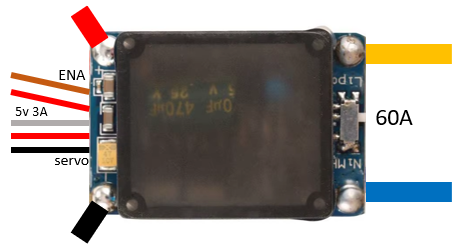
The VKDI20370 ESC has three main connection interfaces: Power Input, Motor Output, and Signal Input.
Power Input and Motor Output
| Pin Name | Description |
|---|---|
| VIN+ | Positive input voltage (connect to battery +) |
| VIN- | Negative input voltage (connect to battery -) |
| MOTOR A | Motor phase A connection |
| MOTOR B | Motor phase B connection |
| MOTOR C | Motor phase C connection |
Signal Input
| Pin Name | Description |
|---|---|
| SIGNAL | PWM signal input from the receiver/controller |
| GND | Ground connection for the signal input |
| 5V OUT | 5V output for powering external devices (optional) |
Usage Instructions
How to Use the VKDI20370 in a Circuit
Connect the Power Supply:
- Connect the positive terminal of the battery to the VIN+ pin.
- Connect the negative terminal of the battery to the VIN- pin.
Connect the Brushless Motor:
- Attach the three motor wires to the MOTOR A, MOTOR B, and MOTOR C pins. The order of connection determines the motor's rotation direction. Swap any two wires to reverse the direction.
Connect the Signal Input:
- Connect the SIGNAL pin to the PWM output of your receiver or microcontroller (e.g., Arduino).
- Connect the GND pin to the ground of your receiver or microcontroller.
Optional 5V Output:
- Use the 5V OUT pin to power external devices, such as a receiver or sensors, if needed.
Power On:
- Ensure all connections are secure, then power on the system. The ESC will initialize and be ready to receive PWM signals.
Important Considerations
- PWM Signal Range: Ensure the PWM signal falls within the 1ms to 2ms range. A 1ms pulse corresponds to minimum throttle, while a 2ms pulse corresponds to maximum throttle.
- Battery Compatibility: Use a battery within the 6V to 20V range to avoid damaging the ESC.
- Cooling: Avoid prolonged operation at peak current (37A) to prevent overheating. Ensure adequate airflow or cooling if used in high-power applications.
- Calibration: Some ESCs require throttle calibration before first use. Refer to the manufacturer's instructions for calibration procedures.
Example: Using VKDI20370 with Arduino UNO
Below is an example of controlling the VKDI20370 ESC with an Arduino UNO using the Servo library.
#include <Servo.h> // Include the Servo library for generating PWM signals

Servo esc; // Create a Servo object to control the ESC

void setup() {
  esc.attach(9); // Attach the ESC signal wire to pin 9 on the Arduino
  esc.writeMicroseconds(1000); // Send minimum throttle (1ms pulse)
  delay(2000); // Wait for 2 seconds to allow the ESC to initialize
}

void loop() {
  esc.writeMicroseconds(1500); // Send a mid-throttle signal (1.5ms pulse)
  delay(5000); // Run the motor at mid-speed for 5 seconds

  esc.writeMicroseconds(2000); // Send maximum throttle (2ms pulse)
  delay(5000); // Run the motor at full speed for 5 seconds

  esc.writeMicroseconds(1000); // Send minimum throttle to stop the motor
  delay(5000); // Wait for 5 seconds before repeating
}
Troubleshooting and FAQs
Common Issues and Solutions
Motor Does Not Spin:
- Cause: Incorrect wiring or no PWM signal.
- Solution: Verify all connections. Ensure the PWM signal is within the 1ms to 2ms range.
Motor Spins in the Wrong Direction:
- Cause: Motor phase wires are connected in the wrong order.
- Solution: Swap any two motor wires (e.g., MOTOR A and MOTOR B).
ESC Overheats:
- Cause: Prolonged operation at high current or insufficient cooling.
- Solution: Reduce the load on the motor or improve cooling (e.g., add a heatsink or fan).
No 5V Output:
- Cause: Overloading the 5V output pin.
- Solution: Ensure the connected device does not exceed the 5V output current rating.
FAQs
Q: Can I use the VKDI20370 with a brushed motor?
A: No, the VKDI20370 is designed specifically for brushless motors.Q: How do I calibrate the throttle range?
A: Refer to the manufacturer's calibration procedure. Typically, you need to power on the ESC while sending maximum and minimum throttle signals sequentially.Q: What happens if I exceed the input voltage range?
A: Exceeding the 20V limit may permanently damage the ESC. Always use a compatible power source.Q: Can I use the ESC without a receiver?
A: Yes, you can control the ESC using a microcontroller like Arduino to generate PWM signals.
This concludes the documentation for the VKDI20370 ESC Regulator. For further assistance, refer to the manufacturer's support resources.