How to Use DHT11: Examples, Pinouts, and Specs
Introduction
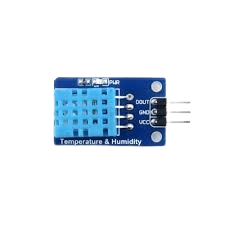
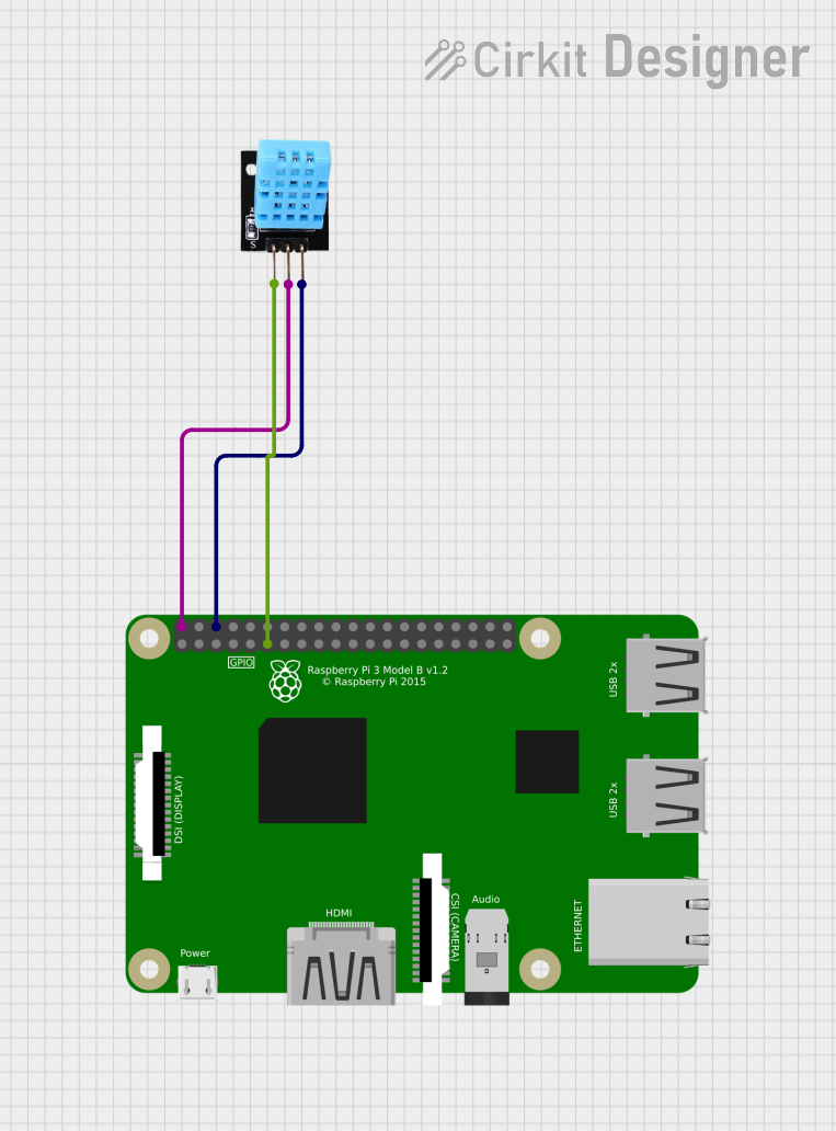
The DHT11 is a widely used digital temperature and humidity sensor that offers a simple interface for measuring ambient temperature and relative humidity. It is a low-cost sensor that is suitable for hobbyist and educational projects, as well as for prototyping and small-scale environmental monitoring applications. The sensor is known for its ease of use and is often interfaced with microcontrollers such as the Arduino UNO.
Explore Projects Built with DHT11
Explore Projects Built with DHT11
Common Applications and Use Cases
- Home weather stations
- HVAC systems monitoring
- Environmental data logging
- Smart home automation
- Educational projects and experiments
Technical Specifications
Key Technical Details
- Supply Voltage: 3 to 5.5 VDC
- Output Signal: Digital signal via a single data pin
- Measurement Range:
- Temperature: 0 to 50°C with ±2°C accuracy
- Humidity: 20 to 90% RH with ±5% RH accuracy
- Resolution:
- Temperature: 1°C
- Humidity: 1% RH
- Sampling Rate: Not more than 1 Hz (once every second)
Pin Configuration and Descriptions
| Pin Number | Name | Description |
|---|---|---|
| 1 | VCC | Power supply (3 to 5.5 VDC) |
| 2 | DATA | Digital data output |
| 3 | NC | Not connected (no function) |
| 4 | GND | Ground |
Usage Instructions
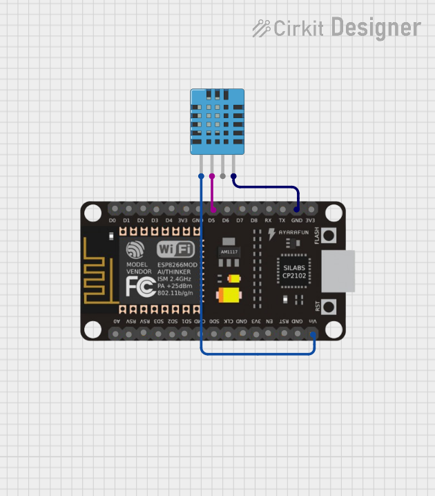
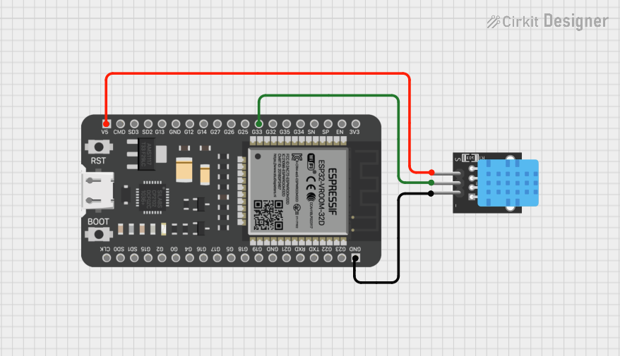
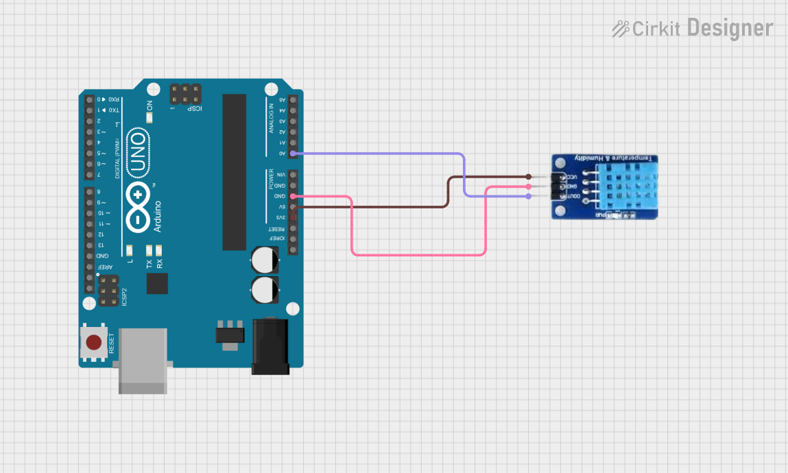
Interfacing with Arduino UNO
Connecting the Sensor:
- Connect the VCC pin to the 5V output on the Arduino.
- Connect the DATA pin to a digital I/O pin, for example, pin 2.
- Connect the GND pin to the ground (GND) on the Arduino.
- A pull-up resistor (typically 4.7kΩ to 10kΩ) is required between the DATA pin and VCC.
Programming the Arduino:
- Include the
DHT.hlibrary in your Arduino sketch. (Install via the Library Manager if not already installed.) - Initialize the sensor by creating an instance of the
DHTclass and specifying the data pin and sensor type (DHT11). - In the
setup()function, begin communication with the sensor using thebegin()method. - In the
loop()function, read the temperature and humidity using thereadHumidity()andreadTemperature()methods.
- Include the
Example Arduino Sketch
#include <DHT.h>

#define DHTPIN 2     // Digital pin connected to the DHT sensor
#define DHTTYPE DHT11 // DHT 11

DHT dht(DHTPIN, DHTTYPE);

void setup() {
  Serial.begin(9600);
  dht.begin();
}

void loop() {
  // Wait a few seconds between measurements.
  delay(2000);

  // Reading temperature or humidity takes about 250 milliseconds!
  float humidity = dht.readHumidity();
  float temperature = dht.readTemperature();

  // Check if any reads failed and exit early (to try again).
  if (isnan(humidity) || isnan(temperature)) {
    Serial.println("Failed to read from DHT sensor!");
    return;
  }

  // Compute heat index in Celsius (isFahrenheit = false)
  float heatIndex = dht.computeHeatIndex(temperature, humidity, false);

  Serial.print("Humidity: ");
  Serial.print(humidity);
  Serial.print("%  Temperature: ");
  Serial.print(temperature);
  Serial.print("°C  Heat index: ");
  Serial.print(heatIndex);
  Serial.println("°C");
}
Important Considerations and Best Practices
- Avoid placing the sensor in direct sunlight or near heat sources to prevent inaccurate readings.
- Ensure that the sensor is not exposed to condensation or water.
- Allow the sensor to acclimatize to the environment for accurate readings.
- Use a pull-up resistor on the data line to ensure reliable data transmission.
Troubleshooting and FAQs
Common Issues
- Inaccurate Readings: Ensure the sensor is not affected by external heat sources and has had time to acclimatize.
- No Data: Check the wiring, especially the pull-up resistor on the data line. Ensure the correct pin is defined in the sketch.
- Intermittent Readings: Ensure a stable power supply and that the sensor is not being read more frequently than once every second.
Solutions and Tips for Troubleshooting
- Verify the connections and the pull-up resistor.
- Check the power supply voltage to ensure it is within the specified range.
- Use the
Serial.print()function to debug and check the values being read from the sensor. - Ensure the Arduino library for the DHT sensor is correctly installed and included in your sketch.
FAQs
Q: Can the DHT11 sensor measure temperature below 0°C or above 50°C? A: No, the DHT11 is limited to a temperature range of 0 to 50°C.
Q: How long should I wait between readings? A: The DHT11 requires a minimum of 1 second between readings for accurate data.
Q: Can I use the DHT11 sensor outdoors? A: The DHT11 can be used outdoors but should be protected from direct sunlight, rain, and condensation.
Q: Is calibration required for the DHT11 sensor? A: The DHT11 comes pre-calibrated from the factory, and no additional calibration is typically required.
Note: The manufacturer part ID "idk" is not a valid identifier. Please provide the correct part ID for more specific information related to the component from the manufacturer. The manufacturer "Arduino" is typically associated with microcontroller boards rather than sensor manufacturing. The DHT11 sensor is produced by various manufacturers and is not an Arduino-specific product.