Cirkit Designer Logo
Cirkit Designer
Your all-in-one circuit design IDE
Home / 
Component Documentation

How to Use micro bit: Examples, Pinouts, and Specs

Image of micro bit
Cirkit Designer LogoDesign with micro bit in Cirkit Designer

Introduction

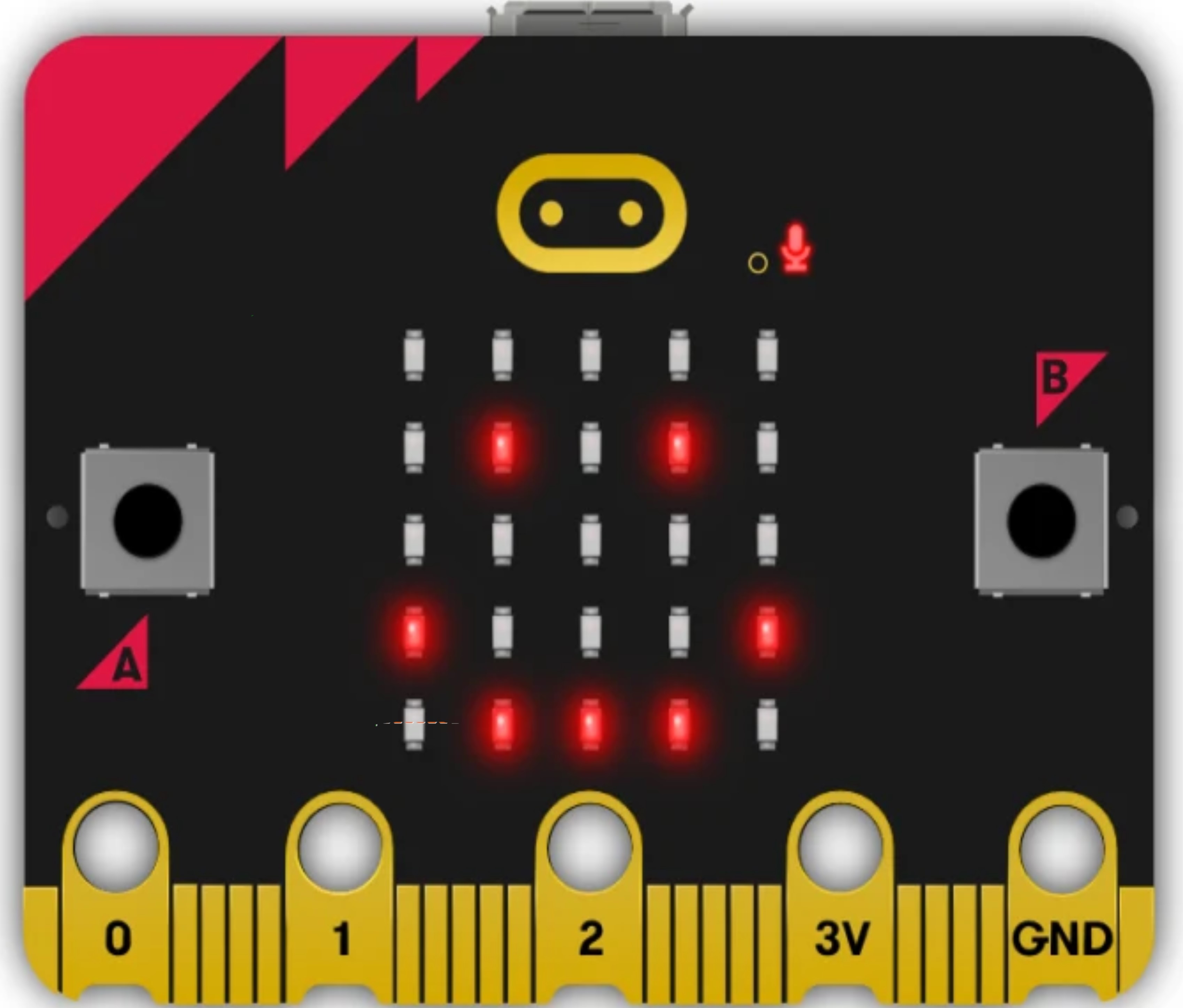
The Micro:bit is a compact microcontroller board designed to make learning and teaching programming and electronics accessible and fun. It is equipped with an ARM Cortex-M0 processor, which provides a balance between performance and power consumption, making it ideal for educational purposes and DIY projects. The Micro:bit is commonly used in schools for teaching coding, robotics, and basic electronics.

Explore Projects Built with micro bit

Use Cirkit Designer to design, explore, and prototype these projects online. Some projects support real-time simulation. Click "Open Project" to start designing instantly!
Adafruit Crickit Controlled Robotics Platform with Micro:bit
Image of Circuit Design for Recyclo-Bot: A project utilizing micro bit in a practical application
This circuit is designed to control multiple motors and servos using an Adafruit Crickit for microbit as the main controller, interfaced with a micro bit microcontroller. It includes two yellow hobby gear motors, two 9G micro servos, and two standard servos, all powered and controlled by the Crickit board. Additionally, there is a 0.96" OLED display for output and a piezo sensor, likely for input, connected to the Crickit, which is programmed via the micro bit.
Cirkit Designer LogoOpen Project in Cirkit Designer
Bluetooth-Controlled Robotic Vehicle with Ultrasonic Obstacle Detection and Motion Sensing
Image of 아두이노 드론: A project utilizing micro bit in a practical application
This circuit features a SparkFun Pro Micro microcontroller interfaced with an L298N DC motor driver to control two DC motors, an HC-SR04 ultrasonic sensor for distance measurement, a Bluetooth module HM-10 for wireless communication, and an MPU-6050 for motion tracking. The Pro Micro is responsible for processing sensor data and managing motor speeds and directions via the motor driver. Power is supplied by a 5V battery connected to the Pro Micro and a separate battery case providing 12V to the motor driver.
Cirkit Designer LogoOpen Project in Cirkit Designer
Micro:bit Controlled Traffic Light Simulation
Image of LED : A project utilizing micro bit in a practical application
This circuit simulates a traffic light system using a micro:bit microcontroller and three LEDs (red, yellow, and green). The micro:bit is programmed to cycle through the LEDs, turning on the green LED for 5 seconds, the yellow LED for 2 seconds, and the red LED for 5 seconds, mimicking the sequence of a real traffic light. The LEDs are connected to the micro:bit's output pins with alligator clip cables, and the micro:bit controls the sequence through its programmed GPIO pins.
Cirkit Designer LogoOpen Project in Cirkit Designer
ATmega328P-Based Sensor Hub with OLED Display and LIDAR
Image of TILTPCB: A project utilizing micro bit in a practical application
This circuit features an Mtiny Uno ATmega328P microcontroller as its central processing unit, interfacing with a variety of sensors and peripherals. It includes a 0.96" OLED display and an MPU6050 accelerometer/gyroscope for user interface and motion sensing, respectively. The circuit also integrates a TF LUNA LIDAR for distance measurement, a DHT11 sensor for temperature and humidity readings, and uses a 9V battery with a 7805 voltage regulator for power management. Communication with a computer for programming and data exchange is facilitated by an Adafruit FTDI Friend module.
Cirkit Designer LogoOpen Project in Cirkit Designer

Explore Projects Built with micro bit

Use Cirkit Designer to design, explore, and prototype these projects online. Some projects support real-time simulation. Click "Open Project" to start designing instantly!
Image of Circuit Design for Recyclo-Bot: A project utilizing micro bit in a practical application
Adafruit Crickit Controlled Robotics Platform with Micro:bit
This circuit is designed to control multiple motors and servos using an Adafruit Crickit for microbit as the main controller, interfaced with a micro bit microcontroller. It includes two yellow hobby gear motors, two 9G micro servos, and two standard servos, all powered and controlled by the Crickit board. Additionally, there is a 0.96" OLED display for output and a piezo sensor, likely for input, connected to the Crickit, which is programmed via the micro bit.
Cirkit Designer LogoOpen Project in Cirkit Designer
Image of 아두이노 드론: A project utilizing micro bit in a practical application
Bluetooth-Controlled Robotic Vehicle with Ultrasonic Obstacle Detection and Motion Sensing
This circuit features a SparkFun Pro Micro microcontroller interfaced with an L298N DC motor driver to control two DC motors, an HC-SR04 ultrasonic sensor for distance measurement, a Bluetooth module HM-10 for wireless communication, and an MPU-6050 for motion tracking. The Pro Micro is responsible for processing sensor data and managing motor speeds and directions via the motor driver. Power is supplied by a 5V battery connected to the Pro Micro and a separate battery case providing 12V to the motor driver.
Cirkit Designer LogoOpen Project in Cirkit Designer
Image of LED : A project utilizing micro bit in a practical application
Micro:bit Controlled Traffic Light Simulation
This circuit simulates a traffic light system using a micro:bit microcontroller and three LEDs (red, yellow, and green). The micro:bit is programmed to cycle through the LEDs, turning on the green LED for 5 seconds, the yellow LED for 2 seconds, and the red LED for 5 seconds, mimicking the sequence of a real traffic light. The LEDs are connected to the micro:bit's output pins with alligator clip cables, and the micro:bit controls the sequence through its programmed GPIO pins.
Cirkit Designer LogoOpen Project in Cirkit Designer
Image of TILTPCB: A project utilizing micro bit in a practical application
ATmega328P-Based Sensor Hub with OLED Display and LIDAR
This circuit features an Mtiny Uno ATmega328P microcontroller as its central processing unit, interfacing with a variety of sensors and peripherals. It includes a 0.96" OLED display and an MPU6050 accelerometer/gyroscope for user interface and motion sensing, respectively. The circuit also integrates a TF LUNA LIDAR for distance measurement, a DHT11 sensor for temperature and humidity readings, and uses a 9V battery with a 7805 voltage regulator for power management. Communication with a computer for programming and data exchange is facilitated by an Adafruit FTDI Friend module.
Cirkit Designer LogoOpen Project in Cirkit Designer

Common Applications and Use Cases

  • Educational tools for teaching programming concepts
  • DIY electronics projects
  • Prototyping IoT (Internet of Things) devices
  • Interactive art and wearables
  • Robotics and automation projects

Technical Specifications

Key Technical Details

  • Processor: 32-bit ARM Cortex-M0 CPU
  • Operating Voltage: 3.0V to 3.6V
  • Input Voltage (VIN): 4.5V to 5.5V
  • Digital I/O Pins: 25 (including 3 large pads for alligator clips)
  • Analog Input Pins: 3
  • PWM Output: Available on certain pins
  • Flash Memory: 256KB
  • RAM: 16KB
  • Connectivity: Bluetooth Low Energy (BLE)
  • Display: 5x5 LED matrix
  • Sensors: Accelerometer, magnetometer, temperature
  • Buttons: 2 user buttons, 1 reset button

Pin Configuration and Descriptions

Pin Number Name Description
1-3 P0-P2 Large I/O pads for alligator clips, also usable as analog inputs
4-16 P3-P16 Digital I/O pins, some support PWM, I2C, SPI
17-18 P19-P20 Dedicated I2C pins for external sensors and components
19 3V 3V power output
20 GND Ground

Usage Instructions

How to Use the Micro:bit in a Circuit

  1. Powering the Micro:bit:

    • Use the USB interface or an external battery pack to power the Micro:bit.
    • Ensure the input voltage does not exceed the specified limits.
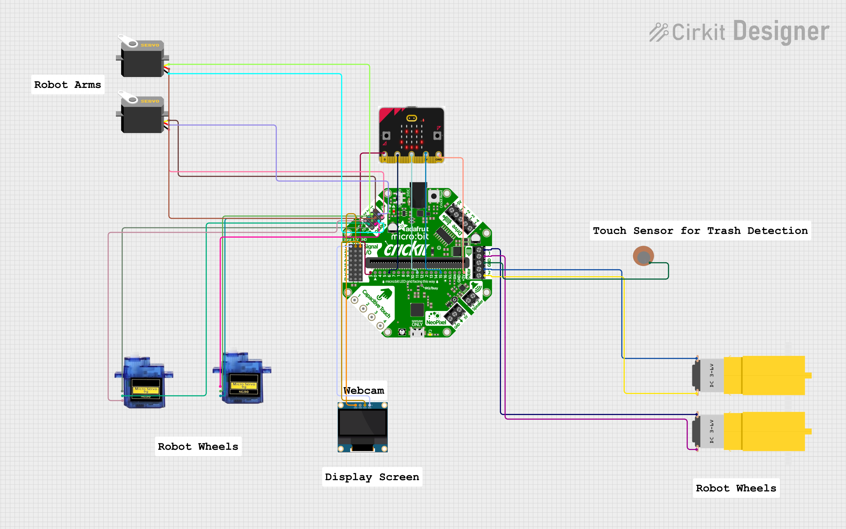
  2. Connecting to External Components:

    • Utilize the edge connector to interface with additional modules and sensors.
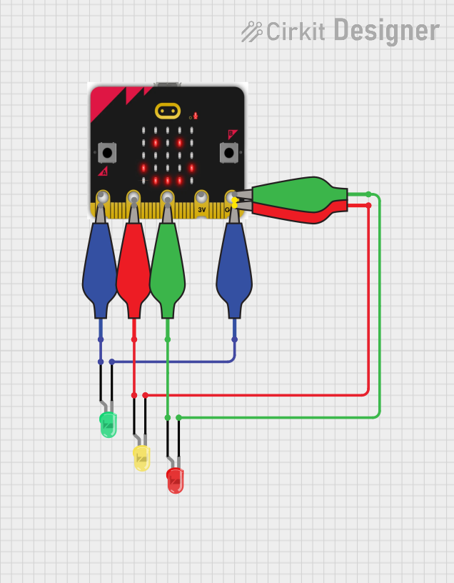
    • The large I/O pads (P0-P2) are designed for easy connection with alligator clips for quick prototyping.
  3. Programming the Micro:bit:

    • The Micro:bit can be programmed using the MakeCode editor, Python, or the mbed platform.
    • Connect the Micro:bit to a computer via USB and follow the specific programming environment's instructions for code deployment.

Important Considerations and Best Practices

  • Always disconnect the Micro:bit from power sources before making or altering connections.
  • Be mindful of the current limitations on the I/O pins to prevent damage to the Micro:bit.
  • When using PWM outputs, ensure that the connected components can handle the signal's power levels.

Troubleshooting and FAQs

Common Issues Users Might Face

  • Micro:bit not recognized by the computer:

    • Check the USB cable and connections.
    • Ensure the appropriate drivers are installed on the computer.
  • Problems uploading code to the Micro:bit:

    • Verify that the Micro:bit is correctly powered and connected.
    • Ensure that the correct board is selected in the programming environment.
  • LED matrix or sensors not working:

    • Check for any visible damage to the board.
    • Ensure that the code is correctly addressing the LED matrix or sensors.

Solutions and Tips for Troubleshooting

  • Restart the Micro:bit and the computer.
  • Try a different USB port or cable.
  • Update the firmware on the Micro:bit if necessary.
  • Consult the Micro:bit community forums for help with specific issues.

FAQs

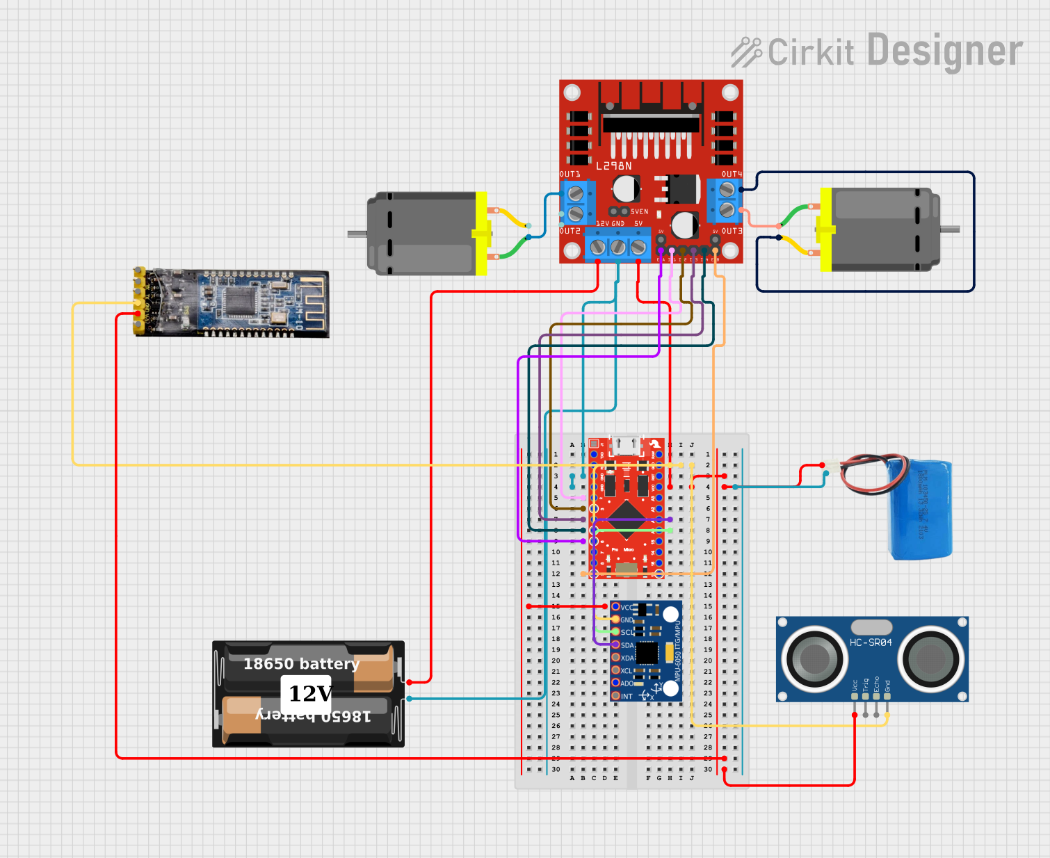
  • Q: Can the Micro:bit be used with an Arduino UNO?

    • A: Yes, the Micro:bit can communicate with an Arduino UNO using serial communication or I2C.
  • Q: What is the maximum current that can be drawn from the 3V pin?

    • A: The maximum current is typically around 90mA, but it is recommended to check the latest specifications from the manufacturer.
  • Q: How do I reset the Micro:bit?

    • A: Press and release the reset button on the back of the Micro:bit.

Example Code for Arduino UNO Communication

// Example code for sending data from an Arduino UNO to a Micro:bit

#include <Wire.h>

void setup() {
  Wire.begin(); // Join the I2C bus as a master
  Serial.begin(9600); // Start serial communication at 9600 baud
}

void loop() {
  Wire.beginTransmission(0x0A); // Begin transmission to a device with address 0x0A
  Wire.write("Hello Micro:bit!"); // Send a string to the Micro:bit
  Wire.endTransmission(); // End transmission

  delay(1000); // Wait for a second
}

Note: The above code is a simple demonstration of I2C communication. The actual implementation may vary based on the specific requirements and configurations of your project. Always refer to the Micro:bit and Arduino UNO documentation for detailed information on compatibility and communication protocols.


Disclaimer: The information provided in this documentation is for educational purposes only. The component manufacturer "aesrers" and part ID "ftydytdtdtty" are fictional and used for illustrative purposes. Always consult the official datasheets and technical resources from the actual manufacturers for accurate and up-to-date information.