How to Use DS3234: Examples, Pinouts, and Specs
Introduction
The DS3234 is a highly accurate real-time clock (RTC) module manufactured by Esparkfun (Part ID: Esparkfun DS3234). It features an integrated temperature sensor, programmable alarms, and SPI communication for fast and reliable data transfer. Designed for low power consumption, the DS3234 is ideal for battery-operated devices and applications requiring precise timekeeping. Additionally, it includes a backup battery feature to maintain timekeeping during power outages.
Explore Projects Built with DS3234


Explore Projects Built with DS3234
Common Applications
- Data logging systems
- Battery-powered devices
- Industrial automation
- Time-stamped data collection
- Alarm systems and scheduling applications
Technical Specifications
The DS3234 offers robust features and specifications to meet the needs of various applications. Below are the key technical details:
Key Technical Details
| Parameter | Value |
|---|---|
| Communication Interface | SPI (Serial Peripheral Interface) |
| Operating Voltage | 2.7V to 5.5V |
| Backup Battery Voltage | 2.3V to 3.7V |
| Current Consumption | 1.2 µA (Timekeeping mode with battery) |
| Timekeeping Accuracy | ±2 ppm (0°C to +40°C) |
| Temperature Sensor Range | -40°C to +85°C |
| Alarm Functions | Programmable alarms (daily, hourly, etc.) |
| Package Type | SOIC-20 |
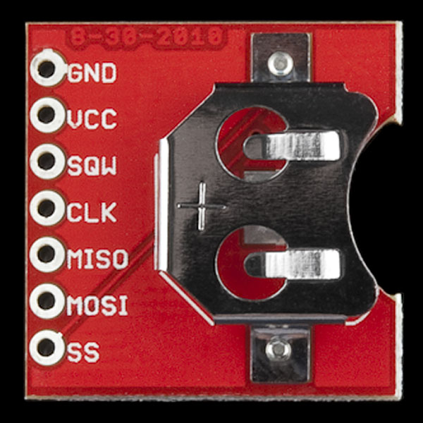
Pin Configuration and Descriptions
The DS3234 has 20 pins, with the most commonly used pins described below:
| Pin Number | Pin Name | Description |
|---|---|---|
| 1 | VCC | Power supply input (2.7V to 5.5V) |
| 2 | GND | Ground |
| 3 | CS | Chip Select (active low) |
| 4 | SCLK | SPI Clock input |
| 5 | MOSI | SPI Master Out Slave In |
| 6 | MISO | SPI Master In Slave Out |
| 7 | INT/SQW | Interrupt or Square Wave Output |
| 8 | VBAT | Backup battery input (2.3V to 3.7V) |
| 9 | RST | Reset input (active low) |
| 10 | 32kHz | 32kHz clock output |
For a complete pinout, refer to the Esparkfun DS3234 datasheet.
Usage Instructions
The DS3234 is straightforward to use in a circuit, especially with microcontrollers like the Arduino UNO. Below are the steps and best practices for integrating the DS3234 into your project.
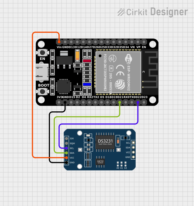
Connecting the DS3234 to an Arduino UNO
- Power Supply: Connect the VCC pin to the 5V pin on the Arduino and GND to ground.
- SPI Communication:
- Connect the CS pin to Arduino pin 10 (or any other digital pin configured as CS).
- Connect the SCLK pin to Arduino pin 13.
- Connect the MOSI pin to Arduino pin 11.
- Connect the MISO pin to Arduino pin 12.
- Backup Battery: Attach a 3V coin cell battery to the VBAT pin to enable timekeeping during power outages.
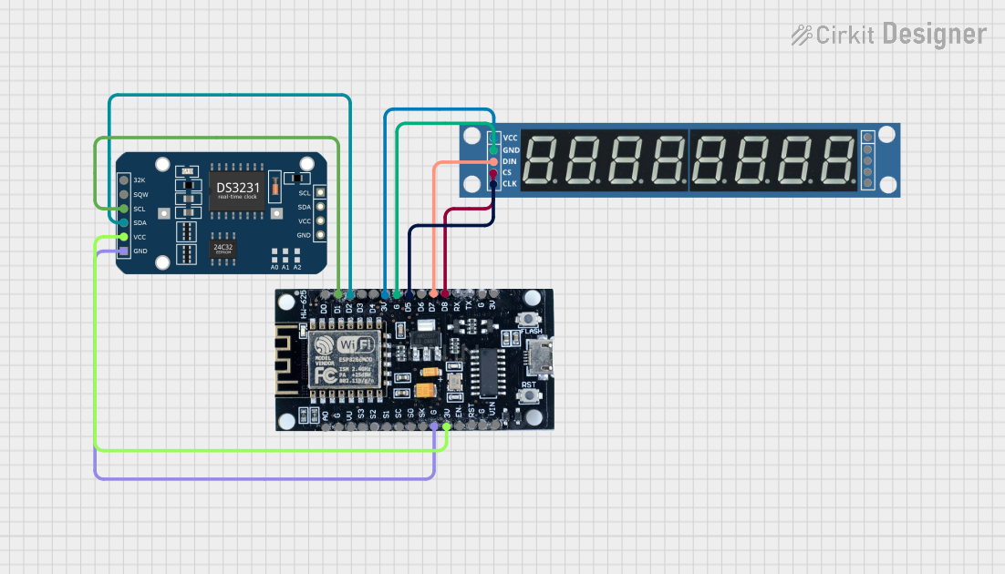
- Interrupts (Optional): Use the INT/SQW pin to trigger alarms or generate a square wave signal.
Sample Arduino Code
Below is an example of how to interface the DS3234 with an Arduino UNO to read the current time:
#include <SPI.h>

// Define DS3234 SPI pins
#define CS_PIN 10  // Chip Select pin for DS3234

void setup() {
  Serial.begin(9600);  // Initialize serial communication
  SPI.begin();         // Initialize SPI communication
  pinMode(CS_PIN, OUTPUT);  // Set CS pin as output
  digitalWrite(CS_PIN, HIGH);  // Set CS pin high (inactive)

  // Initialize DS3234 (e.g., set time, configure alarms, etc.)
  initializeRTC();
}

void loop() {
  // Read and display the current time
  String currentTime = readTime();
  Serial.println("Current Time: " + currentTime);
  delay(1000);  // Wait 1 second before reading again
}

void initializeRTC() {
  // Example: Write initialization code for the DS3234
  digitalWrite(CS_PIN, LOW);  // Select the DS3234
  SPI.transfer(0x8E);         // Address for control register
  SPI.transfer(0x00);         // Disable oscillator stop flag
  digitalWrite(CS_PIN, HIGH); // Deselect the DS3234
}

String readTime() {
  // Example: Read time from the DS3234
  digitalWrite(CS_PIN, LOW);  // Select the DS3234
  SPI.transfer(0x00);         // Address for reading seconds
  byte seconds = SPI.transfer(0x00);  // Read seconds
  digitalWrite(CS_PIN, HIGH); // Deselect the DS3234

  // Convert seconds to a readable format (for simplicity)
  return String(seconds) + " seconds";
}
Best Practices
- Use decoupling capacitors (e.g., 0.1 µF) near the VCC pin to reduce noise.
- Ensure the backup battery is properly connected to maintain timekeeping during power loss.
- Avoid leaving unused pins floating; connect them to GND or VCC as specified in the datasheet.
Troubleshooting and FAQs
Common Issues and Solutions
The DS3234 is not responding to SPI commands.
- Verify the SPI connections (CS, SCLK, MOSI, MISO) and ensure they match the Arduino pin configuration.
- Check that the CS pin is set to LOW before sending SPI commands.
Timekeeping stops when the main power is disconnected.
- Ensure a 3V coin cell battery is connected to the VBAT pin.
- Verify the battery voltage is within the specified range (2.3V to 3.7V).
Incorrect time or date is displayed.
- Confirm that the DS3234 has been initialized with the correct time and date.
- Check for communication errors in the SPI setup.
The INT/SQW pin is not generating interrupts or square waves.
- Verify the configuration of the control register for the desired output.
- Ensure the INT/SQW pin is properly connected to the microcontroller.
FAQs
Q: Can the DS3234 operate without a backup battery?
A: Yes, but it will lose timekeeping functionality during power outages. A backup battery is recommended for uninterrupted operation.
Q: What is the maximum SPI clock speed supported by the DS3234?
A: The DS3234 supports SPI clock speeds up to 4 MHz.
Q: Can I use the DS3234 with a 3.3V microcontroller?
A: Yes, the DS3234 operates within a voltage range of 2.7V to 5.5V, making it compatible with 3.3V systems.
Q: How accurate is the DS3234?
A: The DS3234 has an accuracy of ±2 ppm (parts per million) at 0°C to +40°C, which translates to a deviation of approximately ±1 minute per year.