How to Use ESP8266 12-E: Examples, Pinouts, and Specs
Introduction
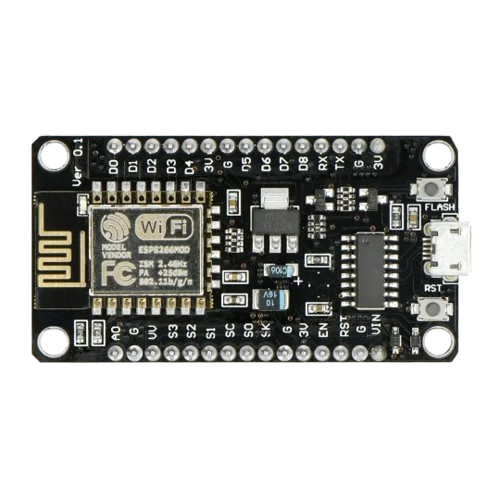
The ESP8266 12-E is a low-cost Wi-Fi microchip developed by ESP8266. It integrates a full TCP/IP stack and microcontroller functionality, making it a versatile solution for Internet of Things (IoT) applications. This module is widely used for projects requiring wireless connectivity, such as smart home devices, remote sensors, and automation systems. Its compact size, low power consumption, and robust feature set make it a popular choice among hobbyists and professionals alike.
Explore Projects Built with ESP8266 12-E
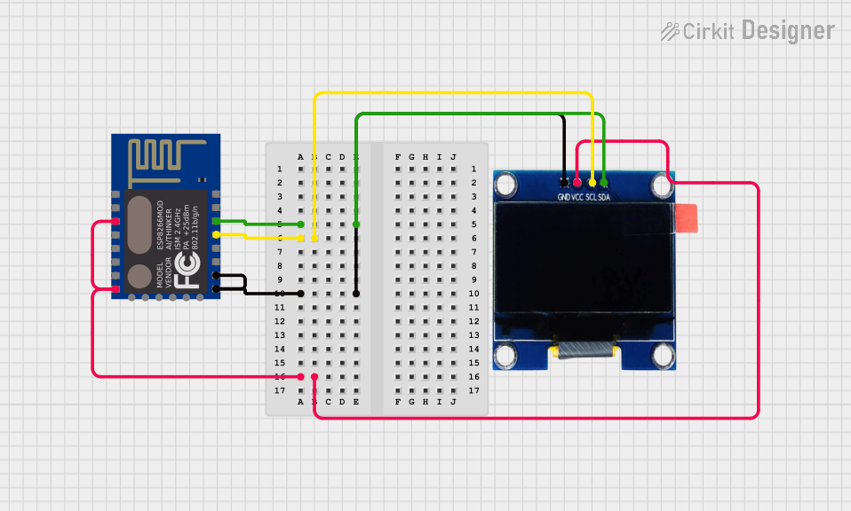
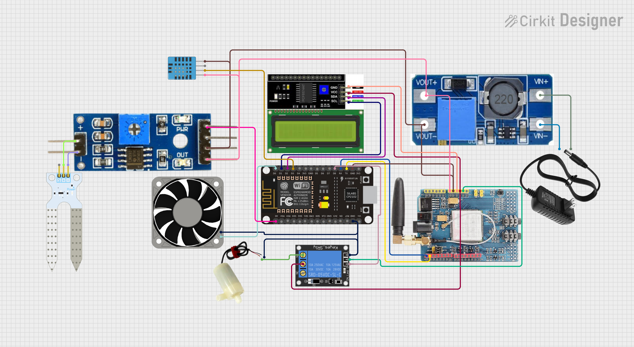
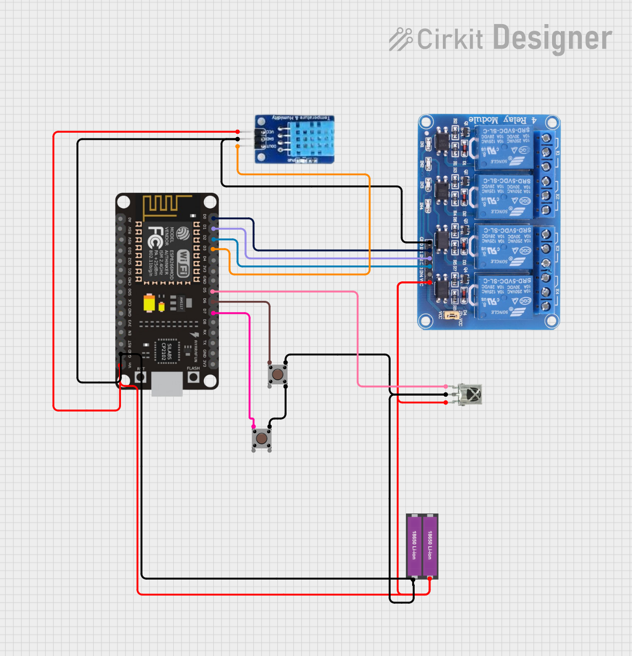
Explore Projects Built with ESP8266 12-E
Common Applications and Use Cases
- IoT devices and smart home automation
- Wireless data logging and monitoring
- Remote control systems
- Web servers and APIs for connected devices
- Prototyping Wi-Fi-enabled embedded systems
Technical Specifications
The ESP8266 12-E module is built around the ESP8266EX chip and offers the following key specifications:
| Parameter | Value |
|---|---|
| Microcontroller | 32-bit Tensilica L106 RISC processor |
| Clock Speed | 80 MHz (default), up to 160 MHz |
| Flash Memory | 4 MB (32 Mbit) |
| RAM | 50 kB for data, 96 kB for instructions |
| Operating Voltage | 3.0V - 3.6V |
| I/O Voltage | 3.3V (not 5V tolerant) |
| Wi-Fi Standards | 802.11 b/g/n |
| Wi-Fi Security | WPA/WPA2 |
| GPIO Pins | 11 (multiplexed with other functions) |
| Communication Protocols | UART, SPI, I2C, PWM, ADC |
| ADC Resolution | 10-bit |
| Power Consumption | 15 µA (deep sleep), 70 mA (active average) |
| Dimensions | 24 mm x 16 mm |
Pin Configuration and Descriptions
The ESP8266 12-E module has 16 pins, each with specific functions. Below is the pinout description:
| Pin | Name | Function |
|---|---|---|
| 1 | GND | Ground (0V reference) |
| 2 | TXD | UART Transmit (TX) for serial communication |
| 3 | RXD | UART Receive (RX) for serial communication |
| 4 | GPIO0 | General-purpose I/O, used for boot mode selection during startup |
| 5 | GPIO2 | General-purpose I/O |
| 6 | GPIO4 | General-purpose I/O |
| 7 | GPIO5 | General-purpose I/O |
| 8 | GPIO12 | General-purpose I/O |
| 9 | GPIO13 | General-purpose I/O |
| 10 | GPIO14 | General-purpose I/O |
| 11 | GPIO15 | General-purpose I/O, must be pulled low during boot |
| 12 | GPIO16 | General-purpose I/O, can be used for deep sleep wake-up |
| 13 | EN (CH_PD) | Chip enable, must be pulled high for normal operation |
| 14 | VCC | Power supply input (3.3V) |
| 15 | ADC (A0) | Analog-to-digital converter input (0-1V range) |
| 16 | RST | Reset pin, active low |
Usage Instructions
How to Use the ESP8266 12-E in a Circuit
- Power Supply: Provide a stable 3.3V power supply to the VCC pin. Ensure the current supply is sufficient (at least 300 mA).
- GPIO Configuration: Connect GPIO0 and GPIO15 appropriately for the desired boot mode:
- For normal operation: GPIO0 = HIGH, GPIO15 = LOW.
- For flashing firmware: GPIO0 = LOW, GPIO15 = LOW.
- Serial Communication: Use the TXD and RXD pins to communicate with a microcontroller or USB-to-serial adapter. Set the baud rate to 115200 (default).
- Pull-Up/Pull-Down Resistors: Use pull-up resistors (10 kΩ) on GPIO0, GPIO2, and EN pins. Use a pull-down resistor on GPIO15.
- Programming: Flash firmware using tools like the Arduino IDE or ESP8266 Flasher.
Important Considerations and Best Practices
- Voltage Levels: The ESP8266 12-E operates at 3.3V. Do not connect 5V signals directly to its pins.
- Power Supply Stability: Use decoupling capacitors (e.g., 10 µF and 0.1 µF) near the VCC pin to ensure stable operation.
- Wi-Fi Antenna: Avoid placing metal objects near the onboard antenna to prevent signal interference.
- Deep Sleep Mode: Use GPIO16 to wake the module from deep sleep for low-power applications.
Example: Connecting to an Arduino UNO
Below is an example of using the ESP8266 12-E with an Arduino UNO to connect to a Wi-Fi network and send data to a server.
Wiring Diagram
| ESP8266 Pin | Arduino Pin |
|---|---|
| VCC | 3.3V |
| GND | GND |
| TXD | RX (via voltage divider) |
| RXD | TX |
| EN | 3.3V |
| GPIO0 | 3.3V |
Arduino Code
#include <SoftwareSerial.h>

// Define RX and TX pins for SoftwareSerial
SoftwareSerial esp8266(2, 3); // RX = Pin 2, TX = Pin 3

void setup() {
  Serial.begin(9600); // Start Serial Monitor
  esp8266.begin(115200); // Start ESP8266 communication

  // Connect to Wi-Fi
  sendCommand("AT+CWJAP=\"YourSSID\",\"YourPassword\"", 5000);
}

void loop() {
  // Example: Send data to a server
  sendCommand("AT+CIPSTART=\"TCP\",\"example.com\",80", 5000);
  sendCommand("AT+CIPSEND=18", 2000);
  sendCommand("GET / HTTP/1.1\r\n\r\n", 2000);
}

void sendCommand(String command, int timeout) {
  esp8266.println(command); // Send command to ESP8266
  long int time = millis();
  while ((time + timeout) > millis()) {
    while (esp8266.available()) {
      char c = esp8266.read(); // Read response from ESP8266
      Serial.print(c); // Print response to Serial Monitor
    }
  }
}
Troubleshooting and FAQs
Common Issues and Solutions
ESP8266 Not Responding to Commands
- Ensure the baud rate matches the module's default (115200).
- Check wiring, especially TX and RX connections.
- Verify that the EN pin is pulled high.
Wi-Fi Connection Fails
- Double-check the SSID and password.
- Ensure the router is within range and supports 2.4 GHz (not 5 GHz).
Module Overheating
- Verify the power supply voltage is 3.3V.
- Use a heat sink or improve ventilation if necessary.
Flashing Firmware Fails
- Ensure GPIO0 is pulled low during flashing.
- Use a reliable USB-to-serial adapter with sufficient current supply.
FAQs
Q: Can the ESP8266 12-E handle 5V logic levels?
A: No, the module is not 5V tolerant. Use a voltage divider or level shifter for 5V signals.Q: How do I reset the module?
A: Pull the RST pin low momentarily to reset the module.Q: What is the maximum range of the Wi-Fi?
A: The range is approximately 50 meters indoors and 100 meters outdoors, depending on the environment.
This concludes the documentation for the ESP8266 12-E module.