
How to Use DP30V5A: Examples, Pinouts, and Specs
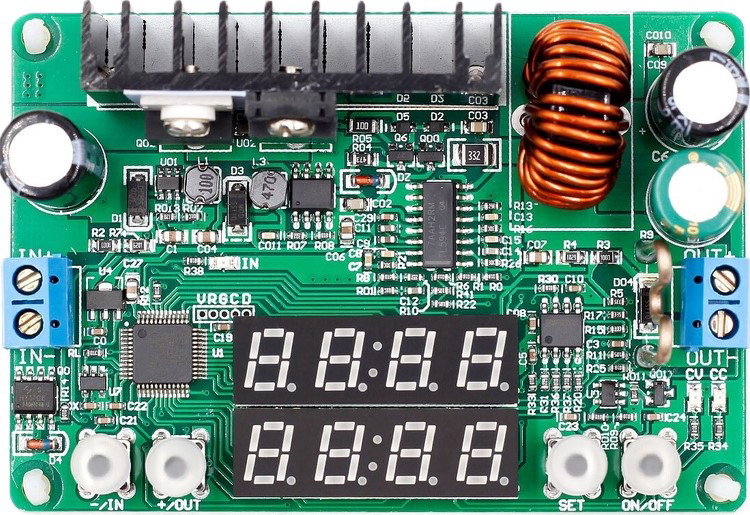
 Design with DP30V5A in Cirkit Designer
Introduction
The DP30V5A is a programmable DC power supply capable of delivering up to 30V and 5A. It is widely used in electronics testing, prototyping, and powering circuits that require precise and adjustable voltage and current settings. This versatile power supply is ideal for hobbyists, engineers, and technicians who need a reliable and customizable power source for their projects.
Explore Projects Built with DP30V5A
 Open Project in Cirkit Designer
 Open Project in Cirkit Designer
 Open Project in Cirkit Designer
 Open Project in Cirkit Designer
Explore Projects Built with DP30V5A
Open Project in Cirkit DesignerOpen Project in Cirkit DesignerOpen Project in Cirkit DesignerOpen Project in Cirkit DesignerCommon Applications
- Powering and testing electronic circuits
- Battery charging with controlled voltage and current
- Laboratory and educational experiments
- Prototyping and debugging electronic devices
- Use in automated test setups
Technical Specifications
The DP30V5A offers a range of features and specifications that make it suitable for various applications. Below are the key technical details:
General Specifications
| Parameter | Value |
|---|---|
| Input Voltage | 6V to 40V DC |
| Output Voltage Range | 0V to 30V DC |
| Output Current Range | 0A to 5A |
| Output Power | Up to 150W |
| Voltage Resolution | 0.01V |
| Current Resolution | 0.001A |
| Display Type | Digital (LCD) |
| Efficiency | Up to 96% |
| Protection Features | Over-voltage, over-current, over-temperature, and short-circuit protection |
Pin Configuration and Descriptions
The DP30V5A module has input and output terminals for connecting to a power source and load. Below is the pin configuration:
| Pin Name | Description |
|---|---|
| VIN+ | Positive input terminal for the DC power source (6V to 40V DC). |
| VIN- | Negative input terminal for the DC power source (ground). |
| VOUT+ | Positive output terminal for the load (adjustable 0V to 30V DC). |
| VOUT- | Negative output terminal for the load (ground). |
| Control Knob | Rotary encoder for adjusting voltage, current, and navigating the menu. |
| LCD Display | Displays voltage, current, power, and settings. |
Usage Instructions
The DP30V5A is easy to use and can be integrated into various setups. Follow the steps below to use the module effectively:
Basic Operation
Connect the Input Power Source:
- Connect a DC power source (6V to 40V) to the
VIN+andVIN-terminals. Ensure the input voltage is within the specified range.
- Connect a DC power source (6V to 40V) to the
Connect the Load:
- Connect the device or circuit you want to power to the
VOUT+andVOUT-terminals.
- Connect the device or circuit you want to power to the
Power On the Module:
- Turn on the input power source. The LCD display will light up, showing the current voltage, current, and power settings.
Adjust Voltage and Current:
- Use the control knob to set the desired output voltage and current.
- Press the knob to switch between voltage and current adjustment modes.
Monitor the Output:
- The LCD display will show real-time output voltage, current, and power. Ensure the load does not exceed the module's maximum ratings.
Important Considerations
- Input Voltage: Ensure the input voltage is at least 1.5V higher than the desired output voltage for proper regulation.
- Heat Dissipation: The module may generate heat during operation. Use a heatsink or active cooling if operating at high power levels for extended periods.
- Protection Features: The module includes built-in protection for over-voltage, over-current, over-temperature, and short circuits. However, avoid intentionally exceeding the module's limits.
Example: Using DP30V5A with Arduino UNO
The DP30V5A can be used to power an Arduino UNO or other microcontroller projects. Below is an example of how to connect and use the module:
- Set the DP30V5A output voltage to 5V (suitable for Arduino UNO).
- Connect the
VOUT+terminal to the Arduino'sVINpin. - Connect the
VOUT-terminal to the Arduino'sGNDpin.
Here is a simple Arduino code example to blink an LED while powered by the DP30V5A:
// Simple LED Blink Example
// This code blinks an LED connected to pin 13 of the Arduino UNO.

void setup() {
  pinMode(13, OUTPUT); // Set pin 13 as an output pin
}

void loop() {
  digitalWrite(13, HIGH); // Turn the LED on
  delay(1000);            // Wait for 1 second
  digitalWrite(13, LOW);  // Turn the LED off
  delay(1000);            // Wait for 1 second
}
Troubleshooting and FAQs
Common Issues and Solutions
No Output Voltage:
- Cause: Input power source is not connected or insufficient.
- Solution: Verify the input voltage is within the 6V to 40V range and properly connected.
Overheating:
- Cause: Prolonged operation at high power without adequate cooling.
- Solution: Attach a heatsink or use a cooling fan to dissipate heat.
Output Voltage Not Stable:
- Cause: Input voltage is too low or fluctuating.
- Solution: Ensure the input voltage is at least 1.5V higher than the desired output voltage.
Module Shuts Down Automatically:
- Cause: Over-current, over-voltage, or over-temperature protection triggered.
- Solution: Check the load and ensure it does not exceed the module's maximum ratings.
FAQs
Q1: Can the DP30V5A be used to charge batteries?
A1: Yes, the DP30V5A can charge batteries. Set the output voltage to the battery's rated voltage and limit the current to a safe value for the battery.
Q2: What happens if I reverse the input polarity?
A2: The DP30V5A includes reverse polarity protection. However, it is recommended to double-check connections to avoid potential damage.
Q3: Can I use the DP30V5A with an AC power source?
A3: No, the DP30V5A requires a DC input. Use an AC-to-DC adapter to provide the required input voltage.
Q4: How accurate are the voltage and current readings?
A4: The DP30V5A provides high accuracy with a voltage resolution of 0.01V and a current resolution of 0.001A. However, for critical applications, verify readings with a calibrated multimeter.
By following this documentation, you can effectively use the DP30V5A programmable DC power supply for a wide range of applications.