Cirkit Designer Logo
Cirkit Designer
Your all-in-one circuit design IDE
Home / 
Component Documentation

How to Use Terminal PCB 2 Pin vcc gnd: Examples, Pinouts, and Specs

Image of Terminal PCB 2 Pin vcc gnd
Cirkit Designer LogoDesign with Terminal PCB 2 Pin vcc gnd in Cirkit Designer

Introduction

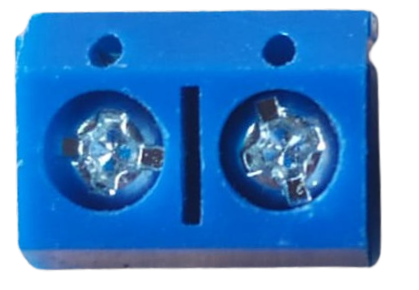
The Terminal PCB 2 Pin VCC GND is a compact and reliable two-pin terminal block designed for connecting power supply lines (VCC and GND) to a printed circuit board (PCB). It provides a secure and robust connection, ensuring stable power delivery to electronic components. This terminal block is widely used in various electronic projects and devices where a simple and efficient power connection is required.

Explore Projects Built with Terminal PCB 2 Pin vcc gnd

Use Cirkit Designer to design, explore, and prototype these projects online. Some projects support real-time simulation. Click "Open Project" to start designing instantly!
High Voltage Generator with Push Switch Activation
Image of Women Safety Device : A project utilizing Terminal PCB 2 Pin vcc gnd in a practical application
This circuit features a high voltage generator connected to a terminal PCB for output, with its power supply controlled by a 2-pin push switch. The high voltage generator's VCC is connected through the switch, allowing the user to turn the high voltage output on and off. The circuit is powered by a 7.4V battery, with the positive terminal connected to the switch and the negative terminal connected to the generator's ground.
Cirkit Designer LogoOpen Project in Cirkit Designer
5-Pin Connector Synchronization Circuit
Image of UMB_Cable: A project utilizing Terminal PCB 2 Pin vcc gnd in a practical application
This circuit consists of four 5-pin connectors, where two of the connectors are fully interconnected pin-to-pin. The purpose of this setup could be to create a parallel connection between the two 5-pin connectors, possibly for signal distribution or redundancy.
Cirkit Designer LogoOpen Project in Cirkit Designer
Pushbutton Interface with General Purpose I/O Plug
Image of Assista GP IO: A project utilizing Terminal PCB 2 Pin vcc gnd in a practical application
This circuit consists of a General Purpose Input/Output (GPIO) plug connected to four pushbuttons. Each pushbutton is wired to a unique input pin on the GPIO plug, allowing the state of each button (pressed or not pressed) to be detected individually. The common terminals of the pushbuttons are interconnected and likely serve as a ground or reference voltage connection.
Cirkit Designer LogoOpen Project in Cirkit Designer
Dual 5V Power Supply Distribution Circuit with Toggle Switch Control
Image of rfdriver: A project utilizing Terminal PCB 2 Pin vcc gnd in a practical application
This circuit consists of two 5V 5A power supplies connected to an AC wall plug point, providing DC output through a 12-way connector. The ground connections from both power supplies are interconnected and also connected to the ground pins of two toggle switches. The DC outputs from the power supplies are separately connected to different pins on the 12-way connector, with each power supply output being switchable via one of the toggle switches.
Cirkit Designer LogoOpen Project in Cirkit Designer

Explore Projects Built with Terminal PCB 2 Pin vcc gnd

Use Cirkit Designer to design, explore, and prototype these projects online. Some projects support real-time simulation. Click "Open Project" to start designing instantly!
Image of Women Safety Device : A project utilizing Terminal PCB 2 Pin vcc gnd in a practical application
High Voltage Generator with Push Switch Activation
This circuit features a high voltage generator connected to a terminal PCB for output, with its power supply controlled by a 2-pin push switch. The high voltage generator's VCC is connected through the switch, allowing the user to turn the high voltage output on and off. The circuit is powered by a 7.4V battery, with the positive terminal connected to the switch and the negative terminal connected to the generator's ground.
Cirkit Designer LogoOpen Project in Cirkit Designer
Image of UMB_Cable: A project utilizing Terminal PCB 2 Pin vcc gnd in a practical application
5-Pin Connector Synchronization Circuit
This circuit consists of four 5-pin connectors, where two of the connectors are fully interconnected pin-to-pin. The purpose of this setup could be to create a parallel connection between the two 5-pin connectors, possibly for signal distribution or redundancy.
Cirkit Designer LogoOpen Project in Cirkit Designer
Image of Assista GP IO: A project utilizing Terminal PCB 2 Pin vcc gnd in a practical application
Pushbutton Interface with General Purpose I/O Plug
This circuit consists of a General Purpose Input/Output (GPIO) plug connected to four pushbuttons. Each pushbutton is wired to a unique input pin on the GPIO plug, allowing the state of each button (pressed or not pressed) to be detected individually. The common terminals of the pushbuttons are interconnected and likely serve as a ground or reference voltage connection.
Cirkit Designer LogoOpen Project in Cirkit Designer
Image of rfdriver: A project utilizing Terminal PCB 2 Pin vcc gnd in a practical application
Dual 5V Power Supply Distribution Circuit with Toggle Switch Control
This circuit consists of two 5V 5A power supplies connected to an AC wall plug point, providing DC output through a 12-way connector. The ground connections from both power supplies are interconnected and also connected to the ground pins of two toggle switches. The DC outputs from the power supplies are separately connected to different pins on the 12-way connector, with each power supply output being switchable via one of the toggle switches.
Cirkit Designer LogoOpen Project in Cirkit Designer

Common Applications and Use Cases

  • Power supply connections in PCB-based circuits
  • Prototyping and DIY electronics projects
  • Industrial control systems
  • Embedded systems and IoT devices
  • Robotics and automation projects

Technical Specifications

The following table outlines the key technical details of the Terminal PCB 2 Pin VCC GND:

Parameter Specification
Number of Pins 2
Pin Labels VCC, GND
Rated Voltage Up to 300V
Rated Current Up to 10A
Pin Pitch 5.08 mm (standard spacing)
Material Plastic housing, copper alloy pins
Mounting Type Through-hole (THT)
Operating Temperature -40°C to +105°C

Pin Configuration and Descriptions

The Terminal PCB 2 Pin VCC GND has two pins, as described in the table below:

Pin Label Description
1 VCC Positive voltage input (power supply)
2 GND Ground connection (return path)

Usage Instructions

How to Use the Component in a Circuit

  1. Soldering the Terminal Block:

    • Insert the two pins of the terminal block into the corresponding through-hole pads on the PCB.
    • Ensure the VCC and GND pins are aligned with the correct power supply traces on the PCB.
    • Solder the pins securely to the PCB to ensure a reliable connection.
  2. Connecting Wires:

    • Strip the insulation from the ends of the power supply wires (VCC and GND).
    • Insert the stripped wire ends into the terminal block's screw clamps.
    • Tighten the screws to secure the wires in place, ensuring a firm connection.
  3. Powering the Circuit:

    • Connect the other ends of the wires to the power source.
    • Double-check the polarity (VCC and GND) to avoid damage to the circuit.
    • Turn on the power supply to energize the circuit.

Important Considerations and Best Practices

  • Polarity Check: Always verify the polarity of the connections (VCC and GND) before powering the circuit to prevent damage to components.
  • Wire Gauge: Use wires of appropriate gauge to handle the current without overheating.
  • Screw Tightening: Ensure the screws are tightened securely to prevent loose connections, which can cause intermittent power issues.
  • Avoid Overloading: Do not exceed the rated voltage and current specifications of the terminal block.

Example: Connecting to an Arduino UNO

The Terminal PCB 2 Pin VCC GND can be used to supply power to an Arduino UNO. Below is an example of how to connect it:

  1. Solder the terminal block to a PCB designed to distribute power to the Arduino.
  2. Connect the VCC pin of the terminal block to the 5V pin of the Arduino.
  3. Connect the GND pin of the terminal block to the GND pin of the Arduino.
  4. Use the following Arduino code to test the power connection:
// Simple Arduino code to test power connection
// This code blinks the onboard LED to confirm the Arduino is powered

void setup() {
  pinMode(LED_BUILTIN, OUTPUT); // Set the onboard LED pin as output
}

void loop() {
  digitalWrite(LED_BUILTIN, HIGH); // Turn the LED on
  delay(1000);                     // Wait for 1 second
  digitalWrite(LED_BUILTIN, LOW);  // Turn the LED off
  delay(1000);                     // Wait for 1 second
}

Troubleshooting and FAQs

Common Issues and Solutions

  1. Loose Connections:

    • Issue: The wires are not securely connected, causing intermittent power delivery.
    • Solution: Ensure the screws are tightened properly and the wires are firmly clamped.
  2. Polarity Reversal:

    • Issue: The VCC and GND connections are swapped, potentially damaging the circuit.
    • Solution: Double-check the polarity of the connections before powering the circuit.
  3. Overheating:

    • Issue: The terminal block or wires become hot during operation.
    • Solution: Verify that the current does not exceed the rated 10A and use appropriate wire gauge.
  4. Poor Solder Joints:

    • Issue: The terminal block is not securely soldered to the PCB, causing unreliable connections.
    • Solution: Re-solder the pins, ensuring a clean and solid joint.

FAQs

Q1: Can this terminal block handle AC power?
A1: Yes, the terminal block can handle both AC and DC power, provided the voltage and current do not exceed the rated specifications.

Q2: What wire sizes are compatible with this terminal block?
A2: The terminal block typically supports wire sizes ranging from 16 AWG to 24 AWG.

Q3: Can I use this terminal block for high-frequency signals?
A3: This terminal block is primarily designed for power connections. For high-frequency signals, consider using connectors specifically designed for signal integrity.

Q4: Is the terminal block reusable?
A4: Yes, the terminal block can be reused, but ensure the screws and clamps remain in good condition for secure connections.