
How to Use Voltage Regulator: Examples, Pinouts, and Specs
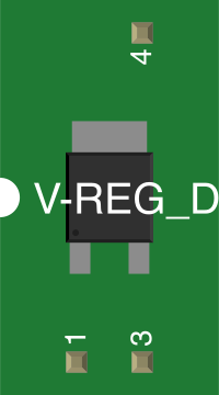
 Design with Voltage Regulator in Cirkit Designer
Introduction
The LM317 is a versatile, adjustable voltage regulator manufactured by Texas Instruments. It is designed to maintain a constant output voltage level, even when there are fluctuations in input voltage or load conditions. This makes it an essential component in power supply circuits, ensuring stable and reliable operation for connected devices.
Explore Projects Built with Voltage Regulator
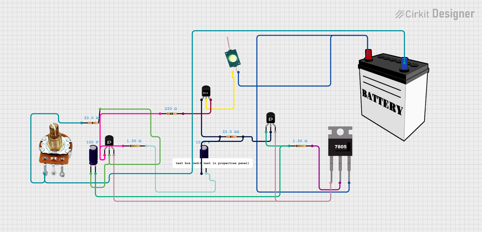 Open Project in Cirkit Designer
 Open Project in Cirkit Designer
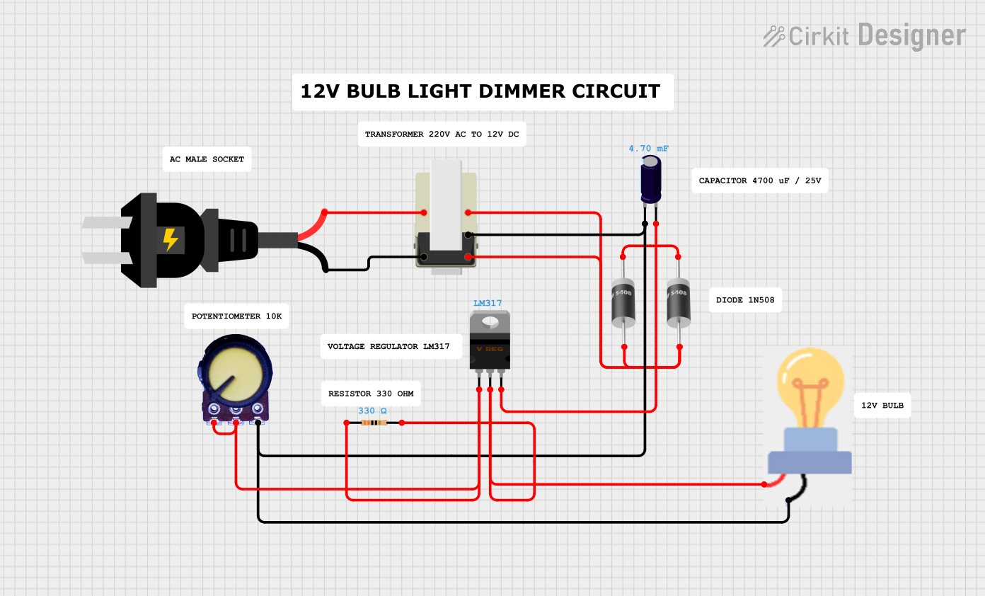 Open Project in Cirkit Designer
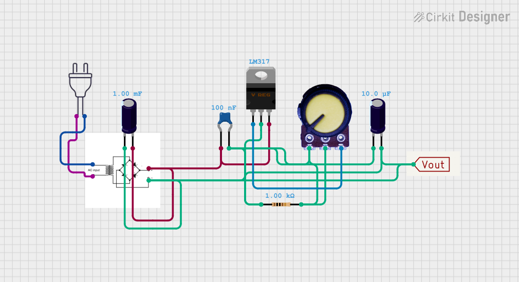 Open Project in Cirkit Designer
Explore Projects Built with Voltage Regulator
Open Project in Cirkit DesignerOpen Project in Cirkit DesignerOpen Project in Cirkit DesignerOpen Project in Cirkit DesignerCommon Applications and Use Cases
- Power supply circuits for electronic devices
- Battery chargers
- Adjustable voltage regulators for laboratory equipment
- Current regulators for LEDs
- Voltage regulation in embedded systems
Technical Specifications
The LM317 is a three-terminal adjustable voltage regulator with the following key specifications:
| Parameter | Value |
|---|---|
| Input Voltage Range | 3 V to 40 V |
| Output Voltage Range | 1.25 V to 37 V |
| Output Current | Up to 1.5 A |
| Line Regulation | 0.01%/V (typical) |
| Load Regulation | 0.1% (typical) |
| Thermal Shutdown | Yes |
| Short-Circuit Protection | Yes |
| Package Types | TO-220, TO-92, SOT-223 |
Pin Configuration and Descriptions
The LM317 has three pins, as described in the table below:
| Pin Number | Pin Name | Description |
|---|---|---|
| 1 | Adjust | Used to set the output voltage via an external resistor divider. |
| 2 | Output | Regulated output voltage. |
| 3 | Input | Unregulated input voltage. |
Usage Instructions
How to Use the LM317 in a Circuit
The LM317 is commonly used in circuits to provide a stable, adjustable output voltage. Below is a step-by-step guide to using the component:
- Connect the Input Voltage: Supply an unregulated DC voltage (3 V to 40 V) to the Input pin.
- Set the Output Voltage: Use a resistor divider network between the Adjust pin and the Output pin to set the desired output voltage. The output voltage is determined by the formula:
[
V_{OUT} = V_{REF} \times \left(1 + \frac{R_2}{R_1}\right) + I_{ADJ} \times R_2
]
where:
- ( V_{REF} ) = 1.25 V (reference voltage)
- ( I_{ADJ} ) = 50 µA (adjustment pin current, typically negligible)
- ( R_1 ) and ( R_2 ) are external resistors.
- Connect the Load: Attach the load to the Output pin.
- Add Capacitors: For stability, connect a 0.1 µF capacitor between the Input pin and ground, and a 1 µF capacitor between the Output pin and ground.
Important Considerations and Best Practices
- Ensure the input voltage is at least 3 V higher than the desired output voltage to maintain proper regulation.
- Use a heatsink if the regulator is expected to dissipate significant power, as the LM317 can generate heat under high current loads.
- Avoid exceeding the maximum input voltage (40 V) or output current (1.5 A) to prevent damage.
- For improved performance, use low-tolerance resistors in the voltage divider network.
Example: Using LM317 with Arduino UNO
The LM317 can be used to power an Arduino UNO by providing a stable 5 V output. Below is an example circuit and Arduino code:
Circuit Setup
- Connect a 12 V DC power supply to the Input pin of the LM317.
- Use ( R_1 = 240 , \Omega ) and ( R_2 = 720 , \Omega ) to set the output voltage to 5 V.
- Connect the Output pin to the Arduino UNO's 5 V pin.
Arduino Code
// Example code to blink an LED using Arduino UNO powered by LM317
const int ledPin = 13; // Pin connected to the onboard LED

void setup() {
  pinMode(ledPin, OUTPUT); // Set the LED pin as an output
}

void loop() {
  digitalWrite(ledPin, HIGH); // Turn the LED on
  delay(1000);               // Wait for 1 second
  digitalWrite(ledPin, LOW);  // Turn the LED off
  delay(1000);               // Wait for 1 second
}
Troubleshooting and FAQs
Common Issues and Solutions
Output Voltage is Incorrect:
- Verify the resistor values in the voltage divider network.
- Ensure the input voltage is at least 3 V higher than the desired output voltage.
Regulator Overheats:
- Check if the load current exceeds 1.5 A.
- Use a heatsink to dissipate heat effectively.
No Output Voltage:
- Confirm proper connections to the input, output, and adjust pins.
- Check for short circuits or damaged components.
Output Voltage is Unstable:
- Add bypass capacitors (0.1 µF and 1 µF) to the input and output pins.
- Ensure the input voltage is stable and within the specified range.
FAQs
Q: Can the LM317 be used as a current regulator?
A: Yes, by connecting a resistor between the Output and Adjust pins, the LM317 can regulate current instead of voltage.
Q: What is the maximum power dissipation of the LM317?
A: The maximum power dissipation depends on the package type and the heatsink used. For the TO-220 package, it is typically around 20 W with proper heatsinking.
Q: Can I use the LM317 for negative voltage regulation?
A: No, the LM317 is designed for positive voltage regulation. For negative voltages, use the LM337.
Q: Is the LM317 suitable for battery charging?
A: Yes, the LM317 can be configured as a constant current source for charging batteries.