How to Use PCA9615: Examples, Pinouts, and Specs
Introduction
The PCA9615 is a dual bidirectional I2C bus buffer designed to extend I2C bus signals over longer distances while maintaining signal integrity. It supports both standard-mode (up to 100 kHz) and fast-mode (up to 400 kHz) I2C communication. By isolating bus capacitance, the PCA9615 ensures reliable data transmission in systems with high capacitance or long cable runs.
Explore Projects Built with PCA9615

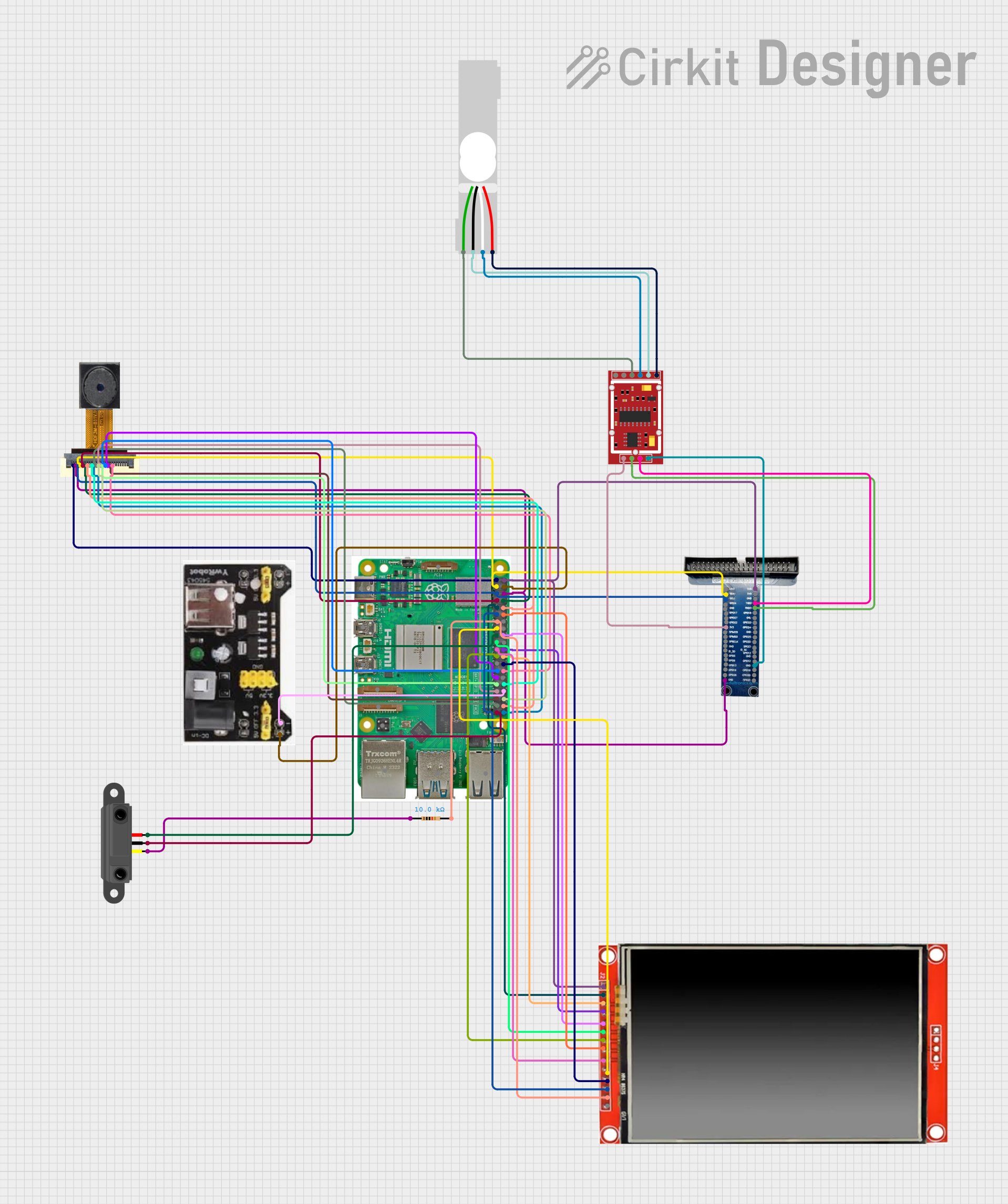
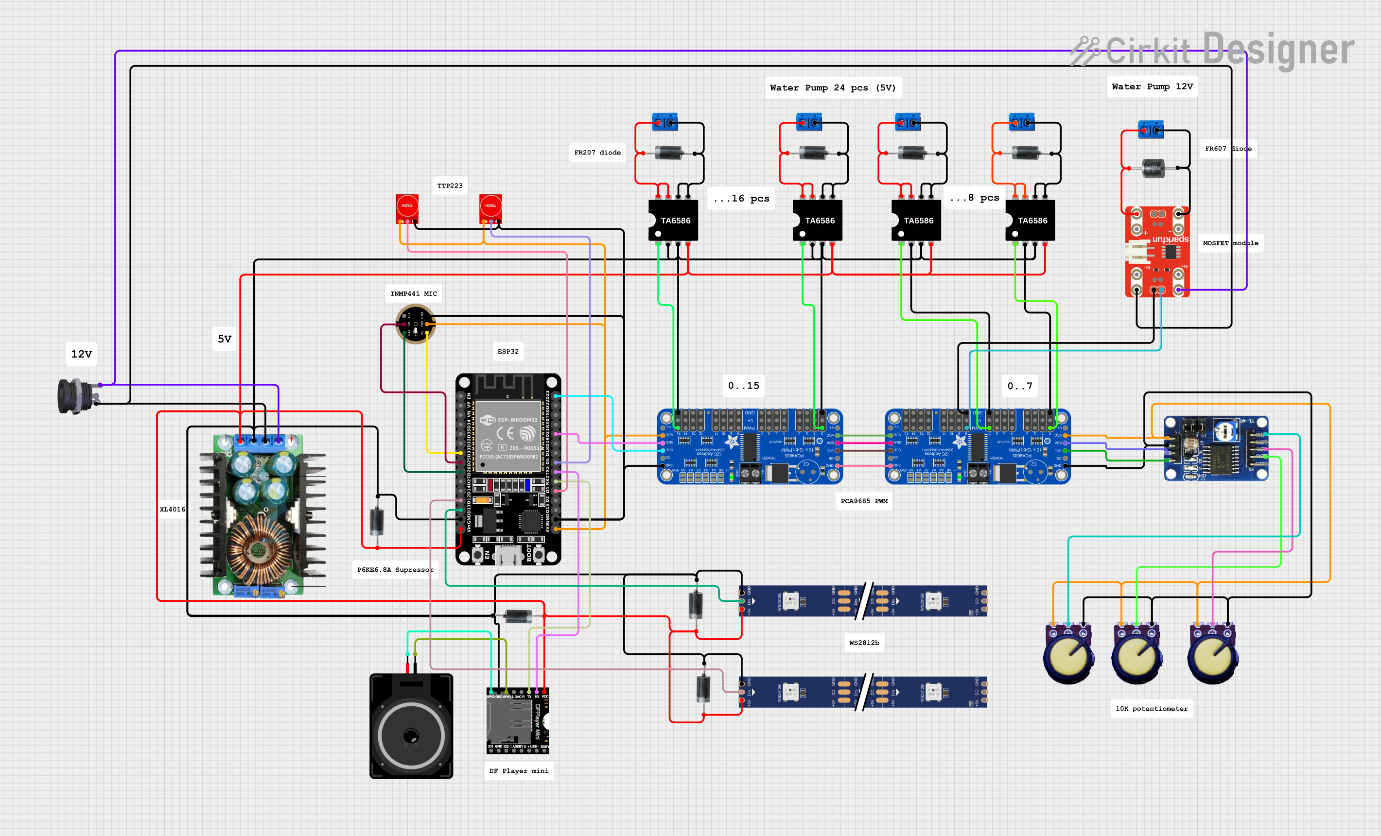
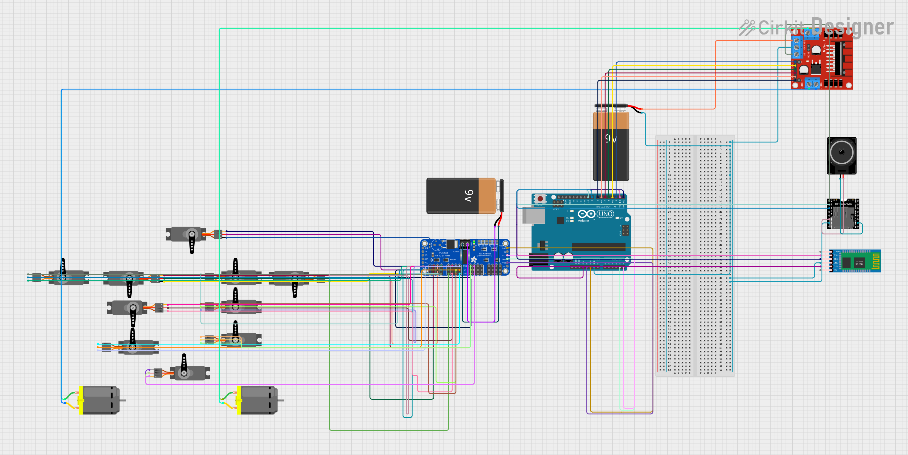
Explore Projects Built with PCA9615
Common Applications and Use Cases
- Extending I2C communication over long distances in industrial environments
- Isolating capacitance between different I2C bus segments
- Improving signal integrity in noisy environments
- Applications in automotive, industrial automation, and embedded systems
Technical Specifications
The PCA9615 is designed to meet the needs of robust I2C communication. Below are its key technical specifications:
| Parameter | Value |
|---|---|
| Supply Voltage (Vcc) | 3.0 V to 5.5 V |
| I2C Bus Speed | Standard-mode (100 kHz) and Fast-mode (400 kHz) |
| Maximum Bus Capacitance | Supports up to 4000 pF per segment |
| Operating Temperature Range | -40°C to +85°C |
| Communication Protocol | I2C |
| Package Type | SOIC-8 |
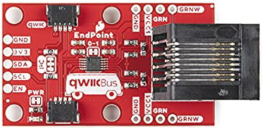
Pin Configuration and Descriptions
The PCA9615 comes in an 8-pin SOIC package. Below is the pinout and description:
| Pin Number | Pin Name | Description |
|---|---|---|
| 1 | VCC | Power supply input (3.0 V to 5.5 V). |
| 2 | A1 | I2C SDA input/output for side A. |
| 3 | A2 | I2C SCL input/output for side A. |
| 4 | GND | Ground connection. |
| 5 | B1 | I2C SDA input/output for side B. |
| 6 | B2 | I2C SCL input/output for side B. |
| 7 | EN | Enable pin. High to enable the buffer, low to disable. |
| 8 | NC | No connection. |
Usage Instructions
The PCA9615 is straightforward to use in I2C systems. Below are the steps and considerations for integrating it into your circuit:
Steps to Use the PCA9615
- Power Supply: Connect the VCC pin to a 3.0 V to 5.5 V power source and the GND pin to ground.
- I2C Bus Connections:
- Connect the SDA and SCL lines of the I2C master to the A1 and A2 pins, respectively.
- Connect the SDA and SCL lines of the I2C slave to the B1 and B2 pins, respectively.
- Enable the Buffer: Pull the EN pin high to enable the buffer. If the EN pin is low, the buffer will be disabled.
- Pull-Up Resistors: Ensure appropriate pull-up resistors are used on both sides of the buffer. The PCA9615 isolates the capacitance of each bus segment, so pull-up resistors are required on both the A and B sides.
- Verify Signal Integrity: Use an oscilloscope to verify that the I2C signals are clean and within the expected voltage levels.
Important Considerations and Best Practices
- Bus Capacitance: The PCA9615 isolates the capacitance of the A and B sides, allowing for higher capacitance on each segment. Ensure the total capacitance on each side does not exceed 4000 pF.
- Cable Length: Use twisted-pair cables for long-distance communication to reduce noise and crosstalk.
- Enable Pin: The EN pin must be pulled high for normal operation. If left floating, the buffer may not function correctly.
- Voltage Compatibility: Ensure that the voltage levels of the I2C devices on both sides of the buffer are compatible with the PCA9615's operating range.
Example: Using PCA9615 with Arduino UNO
Below is an example of how to use the PCA9615 to extend an I2C bus with an Arduino UNO:
Circuit Diagram
- Connect the Arduino's SDA (A4) and SCL (A5) pins to the A1 and A2 pins of the PCA9615.
- Connect the SDA and SCL lines of the I2C slave device to the B1 and B2 pins of the PCA9615.
- Add pull-up resistors (e.g., 4.7 kΩ) to the SDA and SCL lines on both sides of the buffer.
Arduino Code
#include <Wire.h> // Include the Wire library for I2C communication

void setup() {
  Wire.begin(); // Initialize I2C communication
  Serial.begin(9600); // Start serial communication for debugging
  Serial.println("PCA9615 I2C Bus Extension Example");
}

void loop() {
  Wire.beginTransmission(0x3C); // Start communication with I2C slave (address 0x3C)
  Wire.write("Hello, I2C!");    // Send data to the slave device
  Wire.endTransmission();      // End the transmission

  delay(1000); // Wait for 1 second before sending the next message
}
Troubleshooting and FAQs
Common Issues and Solutions
No Communication Between Master and Slave
- Cause: The EN pin is not pulled high.
- Solution: Ensure the EN pin is connected to VCC to enable the buffer.
Signal Distortion or Noise
- Cause: Long cables or improper pull-up resistor values.
- Solution: Use twisted-pair cables for long distances and ensure pull-up resistors are within the recommended range (e.g., 4.7 kΩ to 10 kΩ).
Voltage Level Mismatch
- Cause: The I2C devices on either side of the buffer operate at different voltage levels.
- Solution: Ensure all devices operate within the PCA9615's voltage range (3.0 V to 5.5 V).
Buffer Not Functioning
- Cause: Incorrect wiring or insufficient power supply.
- Solution: Double-check all connections and ensure the power supply is stable and within the specified range.
FAQs
Q1: Can the PCA9615 be used with I2C fast-mode plus (1 MHz)?
A1: No, the PCA9615 supports standard-mode (100 kHz) and fast-mode (400 kHz) I2C communication only.
Q2: Do I need pull-up resistors on both sides of the buffer?
A2: Yes, pull-up resistors are required on both the A and B sides of the buffer to ensure proper operation.
Q3: What is the maximum cable length supported by the PCA9615?
A3: The maximum cable length depends on the capacitance of the cable and the pull-up resistor values. Using twisted-pair cables and proper pull-up resistors can help achieve longer distances.
Q4: Can the PCA9615 be used in noisy environments?
A4: Yes, the PCA9615 is designed to improve signal integrity and is suitable for use in noisy environments.