How to Use Relay 4 12V: Examples, Pinouts, and Specs
Introduction
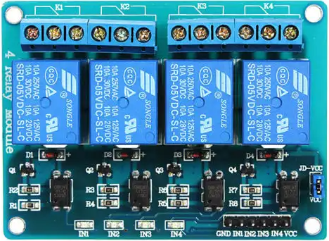
The Relay 4 12V by Levy (Manufacturer Part ID: Relay Module) is a 12V relay module designed for switching electrical circuits on and off. It allows low-voltage control signals to manage higher voltage and current loads, making it an essential component in automation, control systems, and IoT applications. This module features four independent relays, enabling multiple circuits to be controlled simultaneously.
Explore Projects Built with Relay 4 12V


Explore Projects Built with Relay 4 12V
Common Applications
- Home automation systems (e.g., controlling lights, fans, or appliances)
- Industrial control systems
- Robotics and IoT projects
- Motor control
- Security systems (e.g., activating alarms or locks)
Technical Specifications
Key Technical Details
| Parameter | Value |
|---|---|
| Operating Voltage | 12V DC |
| Trigger Voltage | 3.3V to 5V DC (logic level) |
| Maximum Load Voltage | 250V AC / 30V DC |
| Maximum Load Current | 10A |
| Number of Relays | 4 |
| Relay Type | SPDT (Single Pole Double Throw) |
| Isolation | Optocoupler isolation |
| Dimensions | 75mm x 55mm x 20mm |
| Weight | ~60g |
Pin Configuration and Descriptions
The Relay 4 12V module has the following pin configuration:
Input Pins
| Pin Name | Description |
|---|---|
| VCC | Connect to 12V DC power supply to power the relay module. |
| GND | Ground connection for the module. |
| IN1 | Control signal for Relay 1 (active HIGH). |
| IN2 | Control signal for Relay 2 (active HIGH). |
| IN3 | Control signal for Relay 3 (active HIGH). |
| IN4 | Control signal for Relay 4 (active HIGH). |
Output Terminals (for each relay)
| Terminal Name | Description |
|---|---|
| COM | Common terminal for the relay. |
| NO | Normally Open terminal. Circuit is open when the relay is inactive. |
| NC | Normally Closed terminal. Circuit is closed when the relay is inactive. |
Usage Instructions
How to Use the Relay 4 12V in a Circuit
- Power the Module: Connect the VCC pin to a 12V DC power supply and the GND pin to the ground.
- Control Signals: Use a microcontroller (e.g., Arduino UNO) or other logic-level device to send HIGH/LOW signals to the IN1, IN2, IN3, and IN4 pins to control the relays.
- Connect the Load: Attach the load (e.g., light bulb, motor) to the relay's output terminals (COM, NO, NC) based on your desired switching configuration:
- Normally Open (NO): The load is powered only when the relay is activated.
- Normally Closed (NC): The load is powered when the relay is inactive.
- Isolation: Ensure proper isolation between the low-voltage control circuit and the high-voltage load to prevent damage or hazards.
Important Considerations
- Power Supply: Ensure the 12V power supply can provide sufficient current for all four relays when activated simultaneously.
- Load Ratings: Do not exceed the maximum voltage (250V AC / 30V DC) or current (10A) ratings of the relays.
- Flyback Diodes: If controlling inductive loads (e.g., motors), use flyback diodes across the load to protect the relay from voltage spikes.
- Safety: Always handle high-voltage circuits with care and ensure proper insulation.
Example: Using the Relay 4 12V with Arduino UNO
Below is an example code to control the relays using an Arduino UNO:
// Define relay control pins
#define RELAY1 2  // Relay 1 connected to digital pin 2
#define RELAY2 3  // Relay 2 connected to digital pin 3
#define RELAY3 4  // Relay 3 connected to digital pin 4
#define RELAY4 5  // Relay 4 connected to digital pin 5

void setup() {
  // Set relay pins as outputs
  pinMode(RELAY1, OUTPUT);
  pinMode(RELAY2, OUTPUT);
  pinMode(RELAY3, OUTPUT);
  pinMode(RELAY4, OUTPUT);

  // Initialize all relays to OFF state
  digitalWrite(RELAY1, LOW);
  digitalWrite(RELAY2, LOW);
  digitalWrite(RELAY3, LOW);
  digitalWrite(RELAY4, LOW);
}

void loop() {
  // Example: Turn relays ON and OFF sequentially
  digitalWrite(RELAY1, HIGH); // Turn Relay 1 ON
  delay(1000);                // Wait for 1 second
  digitalWrite(RELAY1, LOW);  // Turn Relay 1 OFF

  digitalWrite(RELAY2, HIGH); // Turn Relay 2 ON
  delay(1000);                // Wait for 1 second
  digitalWrite(RELAY2, LOW);  // Turn Relay 2 OFF

  digitalWrite(RELAY3, HIGH); // Turn Relay 3 ON
  delay(1000);                // Wait for 1 second
  digitalWrite(RELAY3, LOW);  // Turn Relay 3 OFF

  digitalWrite(RELAY4, HIGH); // Turn Relay 4 ON
  delay(1000);                // Wait for 1 second
  digitalWrite(RELAY4, LOW);  // Turn Relay 4 OFF
}
Troubleshooting and FAQs
Common Issues and Solutions
Relays Not Activating
- Cause: Insufficient power supply.
- Solution: Ensure the 12V power supply provides adequate current for all relays.
Load Not Switching
- Cause: Incorrect wiring of the load to the relay terminals.
- Solution: Verify the load is connected to the correct terminals (COM, NO, or NC).
Microcontroller Not Controlling Relays
- Cause: Incorrect logic level or wiring.
- Solution: Ensure the control pins (IN1–IN4) are receiving the correct HIGH/LOW signals.
Relay Module Overheating
- Cause: Exceeding the relay's voltage or current ratings.
- Solution: Check the load specifications and ensure they are within the relay's limits.
FAQs
Q: Can I use a 5V power supply instead of 12V?
A: No, the module requires a 12V DC power supply to operate correctly.
Q: Can I control the relays with a 3.3V microcontroller?
A: Yes, the module supports trigger voltages as low as 3.3V, making it compatible with 3.3V logic devices.
Q: Is the module safe for high-voltage applications?
A: Yes, but ensure proper insulation and follow safety guidelines when working with high-voltage circuits.
Q: Can I activate multiple relays simultaneously?
A: Yes, but ensure your power supply can handle the combined current draw of all active relays.