
How to Use relay_5V: Examples, Pinouts, and Specs
 Design with relay_5V in Cirkit Designer
Introduction
A relay_5V is an electromechanical switch that operates at 5 volts. It is designed to control high-power circuits using low-power signals, making it an essential component for applications requiring electrical isolation between the control circuit and the load. The relay consists of a coil, armature, and contacts, which work together to switch the load on or off when the coil is energized.
Explore Projects Built with relay_5V
 Open Project in Cirkit Designer
 Open Project in Cirkit Designer
 Open Project in Cirkit Designer
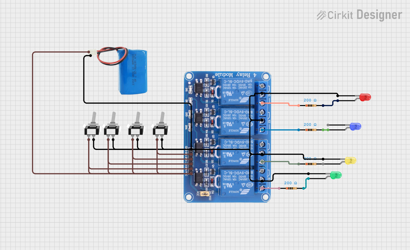 Open Project in Cirkit Designer
Explore Projects Built with relay_5V
Open Project in Cirkit DesignerOpen Project in Cirkit DesignerOpen Project in Cirkit DesignerOpen Project in Cirkit DesignerCommon Applications and Use Cases
- Home automation systems (e.g., controlling lights, fans, or appliances)
- Industrial control systems
- Motor control circuits
- Safety-critical systems requiring electrical isolation
- Interfacing microcontrollers (e.g., Arduino) with high-power devices
Technical Specifications
Below are the key technical details for the relay_5V:
General Specifications
- Operating Voltage (Coil): 5V DC
- Trigger Current (Coil): ~70-100 mA
- Contact Ratings:
- Maximum Voltage: 250V AC / 30V DC
- Maximum Current: 10A
- Electrical Isolation: Yes (between control and load circuits)
- Switching Type: SPDT (Single Pole Double Throw) or DPDT (Double Pole Double Throw), depending on the model
- Relay Type: Electromechanical
- Lifetime: ~100,000 operations (mechanical)
Pin Configuration and Descriptions
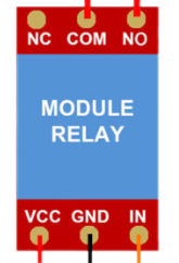
The relay typically has 5 pins for SPDT models. Below is the pin configuration:
| Pin Name | Description |
|---|---|
| Coil+ | Positive terminal of the relay coil (connect to 5V DC) |
| Coil- | Negative terminal of the relay coil (connect to ground) |
| Common (COM) | Common terminal for the load circuit |
| Normally Open (NO) | Open circuit when the relay is de-energized; closed when energized |
| Normally Closed (NC) | Closed circuit when the relay is de-energized; open when energized |
For DPDT relays, there will be an additional set of COM, NO, and NC pins.
Usage Instructions
How to Use the Relay_5V in a Circuit
Power the Relay Coil:
- Connect the
Coil+pin to a 5V DC power source. - Connect the
Coil-pin to ground. - Use a transistor or MOSFET to drive the relay if the control signal comes from a microcontroller (e.g., Arduino), as the relay coil requires more current than most GPIO pins can supply.
- Connect the
Connect the Load:
- Identify whether you want the load to be connected to the
NOorNCterminal. - For devices that should remain off by default, connect the load to the
NOterminal. - For devices that should remain on by default, connect the load to the
NCterminal. - Connect the other side of the load to the power source.
- Identify whether you want the load to be connected to the
Control the Relay:
- Apply a 5V signal to the relay coil to energize it and switch the load circuit.
- Remove the signal to de-energize the relay and return it to its default state.
Important Considerations and Best Practices
- Flyback Diode: Always connect a flyback diode (e.g., 1N4007) across the relay coil terminals to protect the driving circuit from voltage spikes caused by the collapsing magnetic field when the relay is turned off.
- Isolation: Ensure proper electrical isolation between the control and load circuits to prevent damage to sensitive components.
- Current Ratings: Do not exceed the relay's maximum current and voltage ratings to avoid overheating or damage.
- Driving Circuit: Use a transistor or relay driver IC (e.g., ULN2003) to control the relay from a microcontroller.
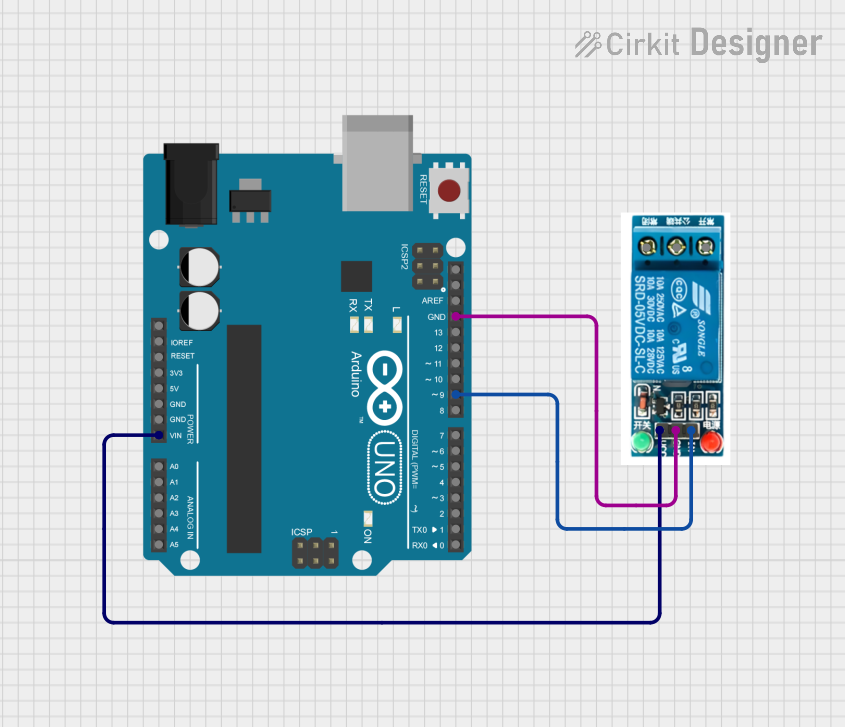
Example: Connecting Relay_5V to an Arduino UNO
Below is an example of how to control a relay_5V using an Arduino UNO:
// Example: Controlling a 5V relay with Arduino UNO
// Pin 7 is used to control the relay

#define RELAY_PIN 7  // Define the pin connected to the relay module

void setup() {
  pinMode(RELAY_PIN, OUTPUT);  // Set the relay pin as an output
  digitalWrite(RELAY_PIN, LOW);  // Ensure the relay is off initially
}

void loop() {
  digitalWrite(RELAY_PIN, HIGH);  // Turn the relay on
  delay(5000);  // Keep the relay on for 5 seconds
  digitalWrite(RELAY_PIN, LOW);  // Turn the relay off
  delay(5000);  // Keep the relay off for 5 seconds
}
Note: Ensure the relay module has an onboard transistor and flyback diode if connecting directly to the Arduino.
Troubleshooting and FAQs
Common Issues and Solutions
Relay Not Switching:
- Cause: Insufficient current to drive the relay coil.
- Solution: Use a transistor or relay driver IC to amplify the control signal.
Load Not Turning On/Off:
- Cause: Incorrect wiring of the load circuit.
- Solution: Verify the connections to the
COM,NO, andNCterminals.
Microcontroller Resetting When Relay Activates:
- Cause: Voltage spikes or noise from the relay coil.
- Solution: Add a flyback diode across the relay coil and use decoupling capacitors near the microcontroller.
Relay Heating Up:
- Cause: Exceeding the relay's current or voltage ratings.
- Solution: Ensure the load does not exceed the relay's specifications.
FAQs
Q: Can I use the relay_5V with a 3.3V microcontroller?
A: Yes, but you will need a transistor or relay driver circuit to step up the control signal to 5V.Q: What is the purpose of the flyback diode?
A: The flyback diode protects the driving circuit from voltage spikes generated when the relay coil is de-energized.Q: Can the relay_5V switch both AC and DC loads?
A: Yes, as long as the load voltage and current are within the relay's rated specifications.Q: How do I know if the relay is energized?
A: Many relay modules include an LED indicator that lights up when the relay is activated.
By following this documentation, you can effectively use the relay_5V in your projects while ensuring safety and reliability.