
How to Use ATMEGA168: Examples, Pinouts, and Specs
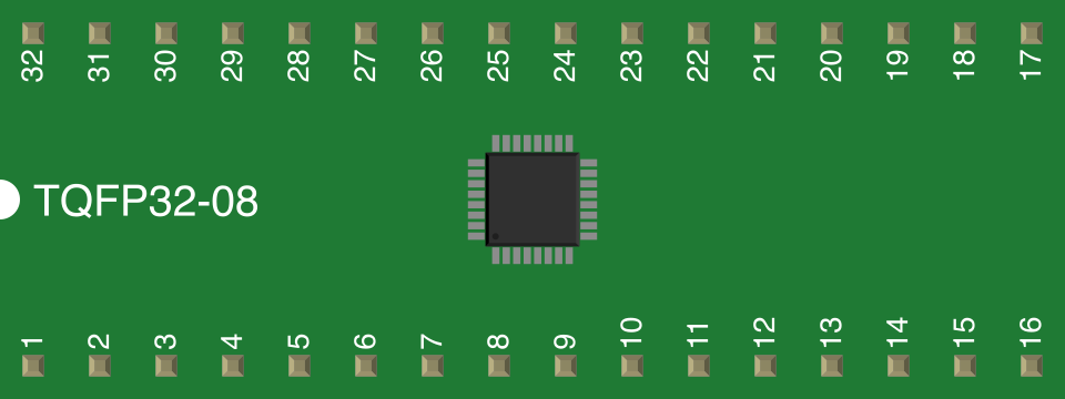
 Design with ATMEGA168 in Cirkit Designer
Introduction
The ATmega168 is a low-power 8-bit microcontroller from Microchip Technology's AVR family. It features 16KB of flash memory, 1KB of SRAM, and 512 bytes of EEPROM. With 23 general-purpose I/O pins, it is highly versatile and widely used in embedded systems, DIY electronics projects, and prototyping. Its compact design and robust feature set make it ideal for applications such as robotics, IoT devices, and home automation.
Explore Projects Built with ATMEGA168
 Open Project in Cirkit Designer
 Open Project in Cirkit Designer
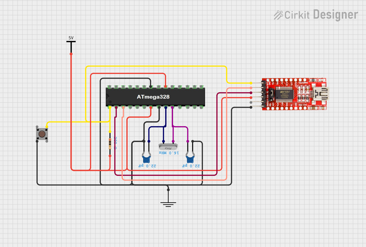 Open Project in Cirkit Designer
 Open Project in Cirkit Designer
Explore Projects Built with ATMEGA168
Open Project in Cirkit DesignerOpen Project in Cirkit DesignerOpen Project in Cirkit DesignerOpen Project in Cirkit DesignerCommon Applications
- Embedded systems and control applications
- DIY electronics and prototyping
- Robotics and automation
- IoT (Internet of Things) devices
- Wearable technology
Technical Specifications
The ATmega168 is designed to deliver high performance while maintaining low power consumption. Below are its key technical details:
Key Features
- Architecture: 8-bit AVR RISC
- Operating Voltage: 1.8V to 5.5V
- Flash Memory: 16KB
- SRAM: 1KB
- EEPROM: 512 bytes
- Clock Speed: Up to 20 MHz
- I/O Pins: 23 general-purpose I/O pins
- Timers: Two 8-bit timers and one 16-bit timer
- ADC: 10-bit, 6-channel Analog-to-Digital Converter
- Communication Interfaces: SPI, I2C (TWI), UART
- Power-Saving Modes: Idle, Power-Down, Power-Save, Standby, and Extended Standby
Pin Configuration and Descriptions
The ATmega168 is available in a 28-pin PDIP package. Below is the pin configuration:
| Pin Number | Pin Name | Description |
|---|---|---|
| 1 | PC6 (RESET) | Reset input (active low) |
| 2 | PD0 (RXD) | UART Receive (Serial Communication) |
| 3 | PD1 (TXD) | UART Transmit (Serial Communication) |
| 4 | PD2 | Digital I/O or External Interrupt (INT0) |
| 5 | PD3 | Digital I/O or External Interrupt (INT1) |
| 6 | PD4 | Digital I/O or Timer/Counter (T0) |
| 7 | VCC | Power Supply Voltage |
| 8 | GND | Ground |
| 9 | PB6 (XTAL1) | External Oscillator Input |
| 10 | PB7 (XTAL2) | External Oscillator Output |
| 11 | PD5 | Digital I/O or Timer/Counter (T1) |
| 12 | PD6 | Digital I/O or PWM Output (OC0A) |
| 13 | PD7 | Digital I/O or PWM Output (OC0B) |
| 14 | PB0 | Digital I/O or SPI (MOSI) |
| 15 | PB1 | Digital I/O or SPI (MISO) |
| 16 | PB2 | Digital I/O or SPI (SCK) |
| 17 | PB3 | Digital I/O or SPI (SS) |
| 18 | PB4 | Digital I/O or Timer/Counter (T2) |
| 19 | PB5 | Digital I/O or PWM Output (OC1A) |
| 20 | AVCC | Analog Power Supply |
| 21 | AREF | Analog Reference Voltage |
| 22 | GND | Ground |
| 23-28 | PC0-PC5 | Analog Inputs or Digital I/O |
Usage Instructions
The ATmega168 can be used in a variety of circuits, from simple LED blinkers to complex embedded systems. Below are the steps and considerations for using the ATmega168:
Basic Circuit Setup
- Power Supply: Connect the VCC pin to a 5V power source and the GND pin to ground.
- Reset Pin: Connect a 10kΩ pull-up resistor to the RESET pin to ensure proper operation.
- Clock Source: Use an external crystal oscillator (e.g., 16 MHz) connected to XTAL1 and XTAL2, along with two 22pF capacitors to ground.
- I/O Pins: Configure the I/O pins as input or output in your code, depending on your application.
- Programming: Use an ISP (In-System Programmer) or Arduino as ISP to upload code to the microcontroller.
Example: Blinking an LED with Arduino UNO
The ATmega168 is compatible with the Arduino IDE. Below is an example of how to blink an LED connected to pin PB5 (digital pin 13 on Arduino):
// Simple LED Blink Example for ATmega168
// Connect an LED to PB5 (digital pin 13) with a 220Ω resistor

void setup() {
  pinMode(13, OUTPUT); // Set pin 13 as an output
}

void loop() {
  digitalWrite(13, HIGH); // Turn the LED on
  delay(1000);            // Wait for 1 second
  digitalWrite(13, LOW);  // Turn the LED off
  delay(1000);            // Wait for 1 second
}
Best Practices
- Use decoupling capacitors (e.g., 0.1µF) near the power pins to reduce noise.
- Avoid leaving unused pins floating; connect them to ground or configure them as inputs with pull-up resistors.
- Use appropriate resistors for LEDs and other components to prevent overcurrent.
Troubleshooting and FAQs
Common Issues
Microcontroller Not Responding
- Cause: Incorrect power supply or missing pull-up resistor on the RESET pin.
- Solution: Verify the power connections and ensure a 10kΩ pull-up resistor is connected to the RESET pin.
Code Upload Fails
- Cause: Incorrect programmer settings or faulty ISP connection.
- Solution: Check the programmer settings in the Arduino IDE and ensure proper wiring between the programmer and the ATmega168.
I/O Pins Not Working
- Cause: Pins not configured correctly in the code.
- Solution: Double-check the
pinMode()configuration in your code.
ADC Not Functioning
- Cause: AREF pin not connected or incorrect reference voltage selected.
- Solution: Connect the AREF pin to the desired reference voltage and configure the ADC settings in the code.
FAQs
Q: Can the ATmega168 run at 3.3V?
- A: Yes, the ATmega168 can operate at 3.3V, but the maximum clock speed is limited to 10 MHz.
Q: How do I reset the ATmega168?
- A: Pull the RESET pin low momentarily to reset the microcontroller.
Q: Can I use the ATmega168 with the Arduino IDE?
- A: Yes, the ATmega168 is fully compatible with the Arduino IDE. Select "Arduino Duemilanove or Diecimila" with the ATmega168 processor in the board settings.
Q: What is the maximum current per I/O pin?
- A: Each I/O pin can source or sink up to 40mA, but it is recommended to limit the current to 20mA for safe operation.
By following this documentation, you can effectively use the ATmega168 in your projects and troubleshoot common issues with ease.