How to Use GSM SIM900: Examples, Pinouts, and Specs
Introduction
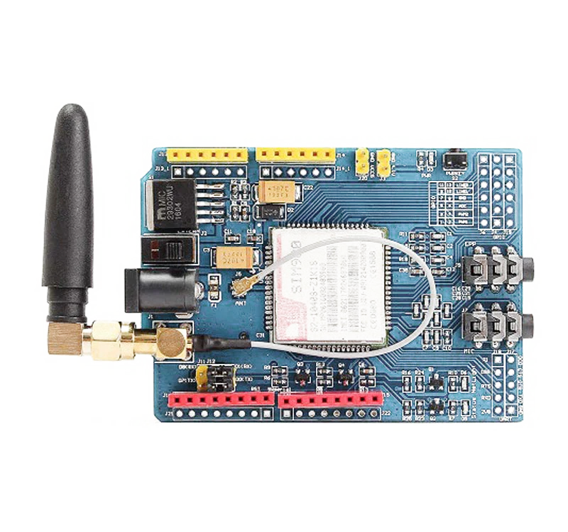
The GSM SIM900 module is a complete Quad-band GSM/GPRS solution in a compact plug-and-play package. It can be used to add cellular communication capabilities to microcontrollers and computers, allowing for voice calls, SMS messages, and data transfer over the GSM network. This makes it an ideal component for applications in remote monitoring systems, IoT devices, and any project requiring mobile connectivity.
Explore Projects Built with GSM SIM900
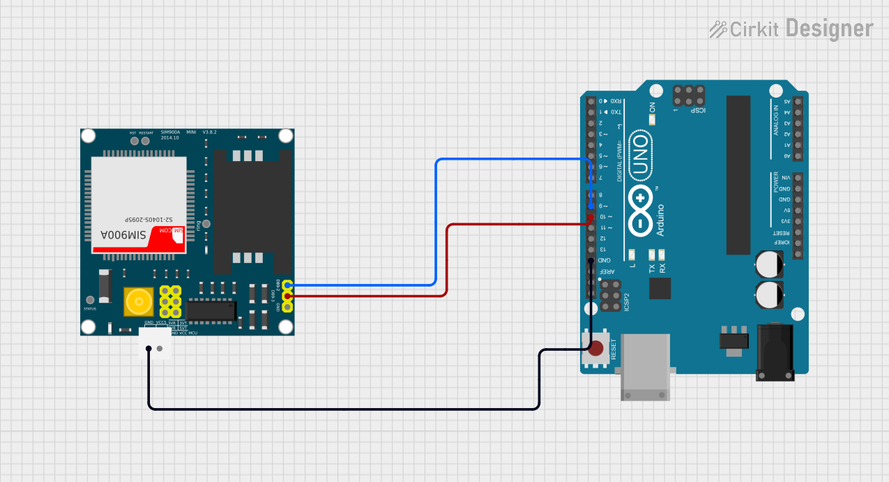
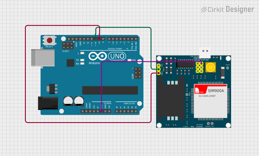
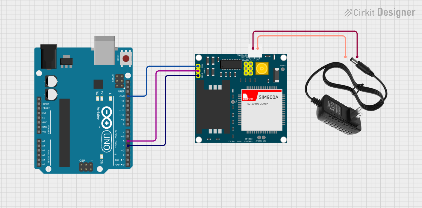
Explore Projects Built with GSM SIM900
Common Applications and Use Cases
- Remote data logging and telemetry
- SMS-based remote control
- Vehicle tracking systems
- IoT devices requiring cellular connectivity
- Emergency response systems
Technical Specifications
Key Technical Details
- Frequency Bands: Quad-band 850/900/1800/1900MHz
- GPRS Multi-slot Class: Class 10/8
- GPRS Mobile Station: Class B
- Compliant to GSM phase 2/2+
- Control via AT commands (GSM 07.07, 07.05, and SIMCOM enhanced AT Commands)
- Low power consumption: 1.5mA(sleep mode)
- Operation temperature: -40°C to +85 °C
Pin Configuration and Descriptions
| Pin Number | Name | Description |
|---|---|---|
| 1 | VCC | Power supply (3.4V to 4.5V) |
| 2 | RST | Reset pin |
| 3 | RXD | Serial data receive pin |
| 4 | TXD | Serial data transmit pin |
| 5 | GND | Ground connection |
Usage Instructions
How to Use the Component in a Circuit
- Power Supply: Connect the VCC pin to a power source that provides a voltage between 3.4V and 4.5V. Ensure that the power supply can deliver enough current for the module's operation.
- Serial Communication: Connect the RXD and TXD pins to the corresponding TX and RX pins of your microcontroller or computer. This will enable serial communication using AT commands.
- Antenna: Attach an appropriate GSM antenna to the module's antenna connector to ensure proper signal reception and transmission.
- SIM Card: Insert a SIM card into the SIM card holder. The SIM card should have an active subscription with a cellular service provider.
Important Considerations and Best Practices
- Always power the module with a clean and stable power source.
- Ensure that the antenna is properly connected and positioned for optimal signal strength.
- Use level shifters if the microcontroller operates at a different logic level than the GSM module.
- Follow ESD precautions when handling the module to avoid damaging sensitive components.
Troubleshooting and FAQs
Common Issues Users Might Face
- Power Issues: If the module does not power on, check the power supply and connections.
- Signal Problems: Poor signal quality can lead to communication failure. Ensure the antenna is properly connected and positioned.
- SIM Card Issues: If the module cannot connect to the network, verify that the SIM card is correctly inserted and activated.
Solutions and Tips for Troubleshooting
- Double-check wiring and solder joints for any loose connections or shorts.
- Use the
AT+CSQcommand to check signal quality. - Reset the module using the RST pin if it becomes unresponsive.
- Consult the SIM900 AT command manual for specific command troubleshooting.
FAQs
Q: Can the SIM900 module connect to 3G or 4G networks? A: No, the SIM900 is a 2G module and can only connect to GSM/GPRS networks.
Q: How do I send an SMS using the SIM900 module?
A: You can send an SMS by issuing the appropriate AT commands (AT+CMGS) through the serial interface.
Q: What is the baud rate for serial communication with the SIM900?
A: The default baud rate is 9600 bps, but it can be configured with the AT+IPR command.
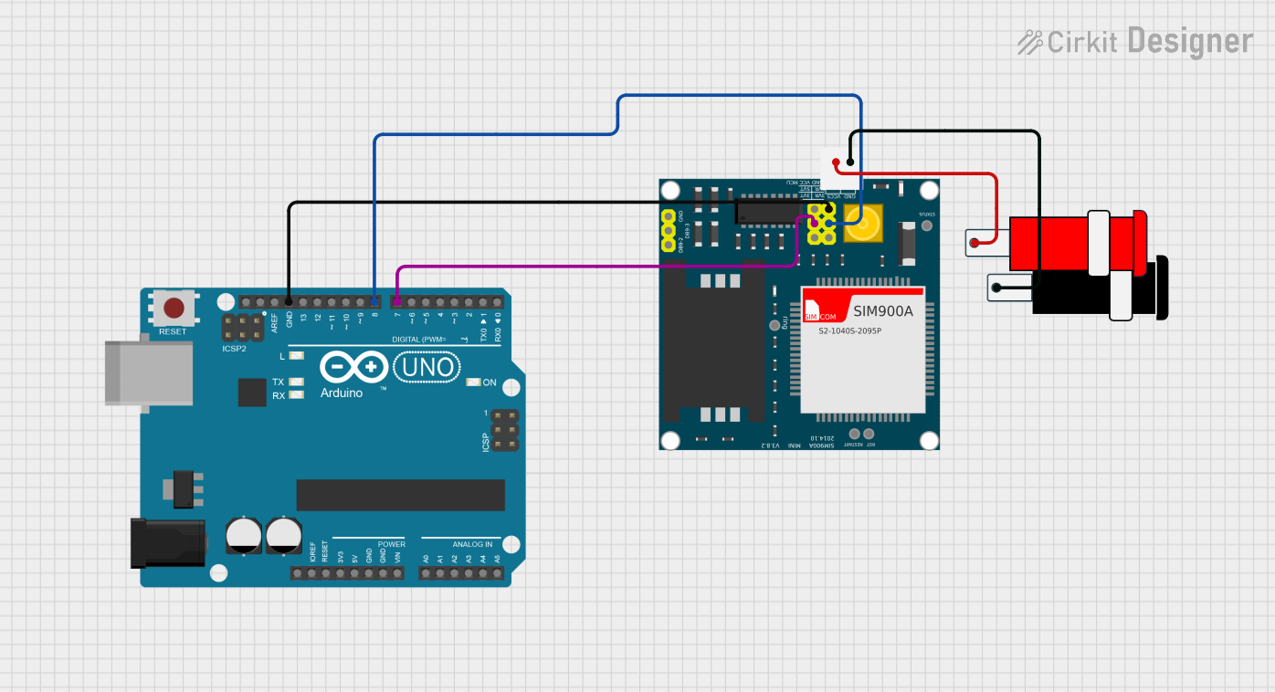
Example Arduino UNO Connection and Code
#include <SoftwareSerial.h>

SoftwareSerial SIM900(7, 8); // RX, TX

void setup() {
  // Begin serial communication with Arduino and Arduino IDE (Serial Monitor)
  Serial.begin(9600);

  // Begin serial communication with Arduino and SIM900
  SIM900.begin(9600);

  // Give time to SIM900 to initialize
  delay(20000);

  // AT command to set SIM900 to SMS mode
  SIM900.print("AT+CMGF=1\r");
  delay(100);

  // Set module to send SMS data to serial out upon receipt
  SIM900.print("AT+CNMI=2,2,0,0,0\r");
  delay(100);
}

void loop() {
  // Check if SIM900 is sending a message
  if (SIM900.available()) {
    Serial.write(SIM900.read());
  }
  // Check if the serial monitor is sending a message
  if (Serial.available()) {
    SIM900.write(Serial.read());
  }
}
Note: This example sets up the SIM900 module to send and receive SMS messages. The SoftwareSerial library is used to create a serial connection on pins 7 and 8 of the Arduino UNO. Ensure that the SIM900 module is powered correctly and that the antenna is connected before running the code.