How to Use USB-B to uart: Examples, Pinouts, and Specs
Introduction
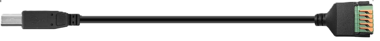
The USB-B to UART converter, manufactured by Arduino, is a versatile electronic component designed to facilitate serial communication between a USB device and a UART (Universal Asynchronous Receiver-Transmitter) interface. This converter enables seamless data transfer between microcontrollers, such as Arduino boards, and computers, making it an essential tool for debugging, programming, and data logging applications.
Explore Projects Built with USB-B to uart

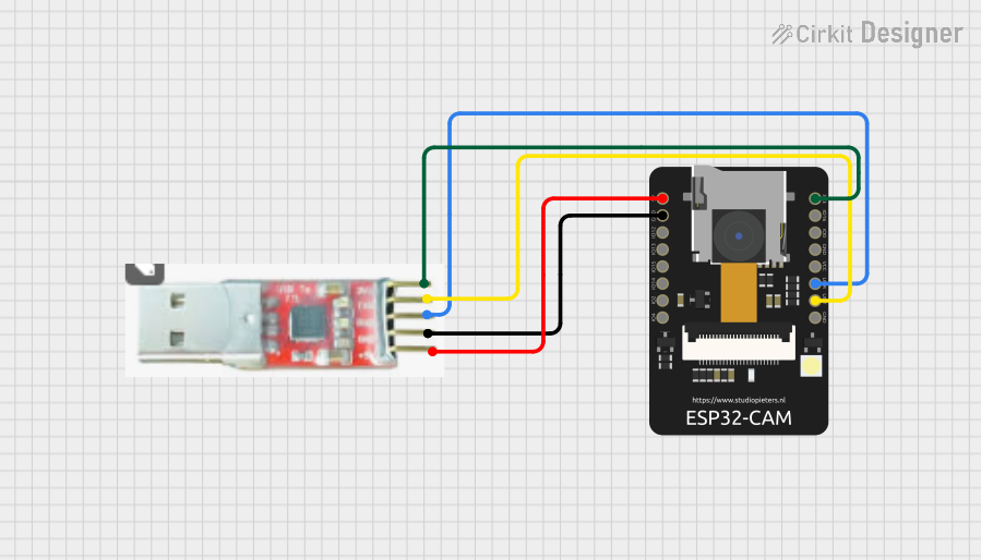
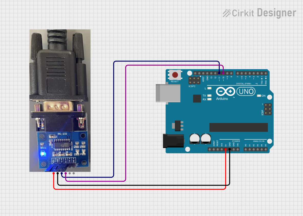
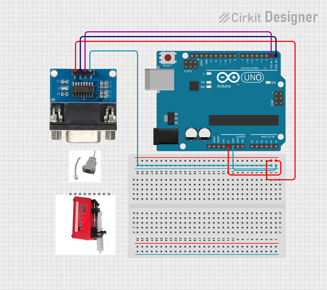
Explore Projects Built with USB-B to uart
Common Applications and Use Cases
- Programming and debugging microcontrollers via a USB interface.
- Establishing serial communication between a computer and embedded systems.
- Data logging and monitoring in IoT (Internet of Things) applications.
- Interfacing legacy UART-based devices with modern USB-enabled systems.
Technical Specifications
The USB-B to UART converter is designed to meet the needs of both hobbyists and professionals. Below are its key technical details:
General Specifications
| Parameter | Value |
|---|---|
| Manufacturer | Arduino |
| USB Connector Type | USB-B |
| UART Voltage Levels | 3.3V and 5V (selectable) |
| Baud Rate Support | 300 bps to 1 Mbps |
| Operating Voltage | 5V (via USB power) |
| Current Consumption | ~50 mA |
| Operating Temperature | -40°C to 85°C |
| Dimensions | 50mm x 20mm x 10mm |
Pin Configuration and Descriptions
The USB-B to UART converter typically features a 6-pin header for UART communication. Below is the pinout:
| Pin Number | Pin Name | Description |
|---|---|---|
| 1 | GND | Ground connection |
| 2 | VCC | Power output (3.3V or 5V, selectable via jumper) |
| 3 | TXD | Transmit data (UART output) |
| 4 | RXD | Receive data (UART input) |
| 5 | RTS | Request to send (optional flow control) |
| 6 | CTS | Clear to send (optional flow control) |
Usage Instructions
How to Use the Component in a Circuit
- Connect the USB-B Port: Plug the USB-B connector into your computer using a USB cable.
- Connect the UART Pins: Use jumper wires to connect the TXD, RXD, and GND pins to the corresponding pins on your microcontroller or UART-enabled device:
- TXD on the converter connects to RXD on the microcontroller.
- RXD on the converter connects to TXD on the microcontroller.
- GND on the converter connects to GND on the microcontroller.
- Power the Circuit: The converter can provide 3.3V or 5V power to your circuit. Select the desired voltage using the onboard jumper and connect the VCC pin to your device if needed.
- Install Drivers: If required, install the appropriate USB-to-UART drivers on your computer. Arduino boards typically use the CH340 or FTDI drivers.
- Open a Serial Monitor: Use software like the Arduino IDE, PuTTY, or a custom application to send and receive data over the serial connection.
Important Considerations and Best Practices
- Voltage Compatibility: Ensure the voltage levels of the UART interface match your microcontroller's requirements (3.3V or 5V).
- Cross-Connect TXD and RXD: Always connect TXD to RXD and vice versa between the converter and the microcontroller.
- Avoid Overloading: Do not draw excessive current from the VCC pin to power external devices.
- Secure Connections: Use reliable jumper wires or soldered connections to avoid communication errors due to loose connections.
Example Code for Arduino UNO
Below is an example of how to use the USB-B to UART converter with an Arduino UNO to send and receive data:
// Example: Serial communication between Arduino UNO and USB-B to UART converter

void setup() {
  Serial.begin(9600); // Initialize serial communication at 9600 baud
  Serial.println("USB-B to UART Converter Test");
  // Send a test message to the serial monitor
}

void loop() {
  if (Serial.available() > 0) {
    // Check if data is available to read from the serial monitor
    char receivedChar = Serial.read();
    // Read the incoming character
    Serial.print("Received: ");
    Serial.println(receivedChar);
    // Echo the received character back to the serial monitor
  }
}
Troubleshooting and FAQs
Common Issues and Solutions
No Communication Between Devices
- Cause: Incorrect TXD and RXD connections.
- Solution: Verify that TXD on the converter is connected to RXD on the microcontroller, and RXD on the converter is connected to TXD on the microcontroller.
Device Not Recognized by Computer
- Cause: Missing or incorrect USB-to-UART drivers.
- Solution: Install the appropriate drivers for your operating system (e.g., CH340 or FTDI drivers).
Data Corruption or Noise
- Cause: Mismatched baud rates or loose connections.
- Solution: Ensure the baud rate in your code matches the settings in your serial monitor. Check all connections for stability.
Power Issues
- Cause: Excessive current draw from the VCC pin.
- Solution: Use an external power source if your circuit requires more current than the converter can provide.
FAQs
Q: Can I use this converter with a 3.3V microcontroller?
A: Yes, the converter supports both 3.3V and 5V logic levels. Use the onboard jumper to select the appropriate voltage.
Q: What is the maximum cable length for the USB connection?
A: The USB cable length should not exceed 5 meters to ensure reliable communication.
Q: Can I use this converter for SPI or I2C communication?
A: No, this converter is designed specifically for UART communication and does not support SPI or I2C protocols.
Q: How do I check if the drivers are installed correctly?
A: On Windows, open the Device Manager and look for the converter under "Ports (COM & LPT)." On macOS or Linux, use the ls /dev/tty* command to find the device.
By following this documentation, you can effectively use the Arduino USB-B to UART converter for a wide range of serial communication applications.