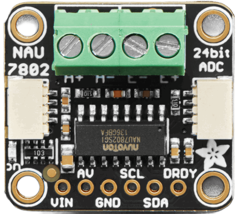
How to Use NAU7802 Load Cell ADC: Examples, Pinouts, and Specs
Introduction
The NAU7802 is a high-precision, low-power analog-to-digital converter (ADC) designed specifically for load cell applications. It features a built-in programmable gain amplifier (PGA) and offers a 24-bit resolution, making it ideal for accurate weight measurement in various applications. This component is widely used in digital weighing scales, industrial process control, and other applications requiring precise weight or force measurements.
Explore Projects Built with NAU7802 Load Cell ADC

Explore Projects Built with NAU7802 Load Cell ADC
Common Applications:
- Digital weighing scales
- Industrial process control systems
- IoT-based weight monitoring
- Laboratory measurement equipment
- Force-sensitive applications
Technical Specifications
The NAU7802 is designed to deliver high performance while maintaining low power consumption. Below are its key technical details:
Key Features:
- Resolution: 24-bit ADC
- Input Voltage Range: 2.7V to 5.5V
- Operating Current: 1.2mA (typical)
- Standby Current: 1µA (typical)
- Programmable Gain Amplifier (PGA): Gains of 1, 2, 4, 8, 16, 32, 64, 128
- Communication Interface: I²C (up to 400kHz)
- Temperature Range: -40°C to +85°C
- Integrated Oscillator: 2.5MHz
- Common Mode Rejection Ratio (CMRR): 100dB (typical)
Pin Configuration and Descriptions
The NAU7802 is typically available in a 16-pin QFN package. Below is the pinout description:
| Pin | Name | Type | Description |
|---|---|---|---|
| 1 | AVDD | Power | Analog power supply (2.7V to 5.5V). |
| 2 | AVSS | Ground | Analog ground. |
| 3 | VREFP | Input | Positive reference voltage for ADC. |
| 4 | VREFN | Input | Negative reference voltage for ADC. |
| 5 | AIN1+ | Input | Positive input for differential channel 1. |
| 6 | AIN1- | Input | Negative input for differential channel 1. |
| 7 | AIN2+ | Input | Positive input for differential channel 2. |
| 8 | AIN2- | Input | Negative input for differential channel 2. |
| 9 | DVDD | Power | Digital power supply (2.7V to 5.5V). |
| 10 | DVSS | Ground | Digital ground. |
| 11 | SDA | I/O | I²C data line. |
| 12 | SCL | Input | I²C clock line. |
| 13 | DRDY | Output | Data ready signal (active low). |
| 14 | CS | Input | Chip select (active low). |
| 15 | RESET | Input | Reset pin (active low). |
| 16 | XTAL1/XTAL2 | Input/Output | External crystal oscillator pins (optional, for custom clock configurations). |
Usage Instructions
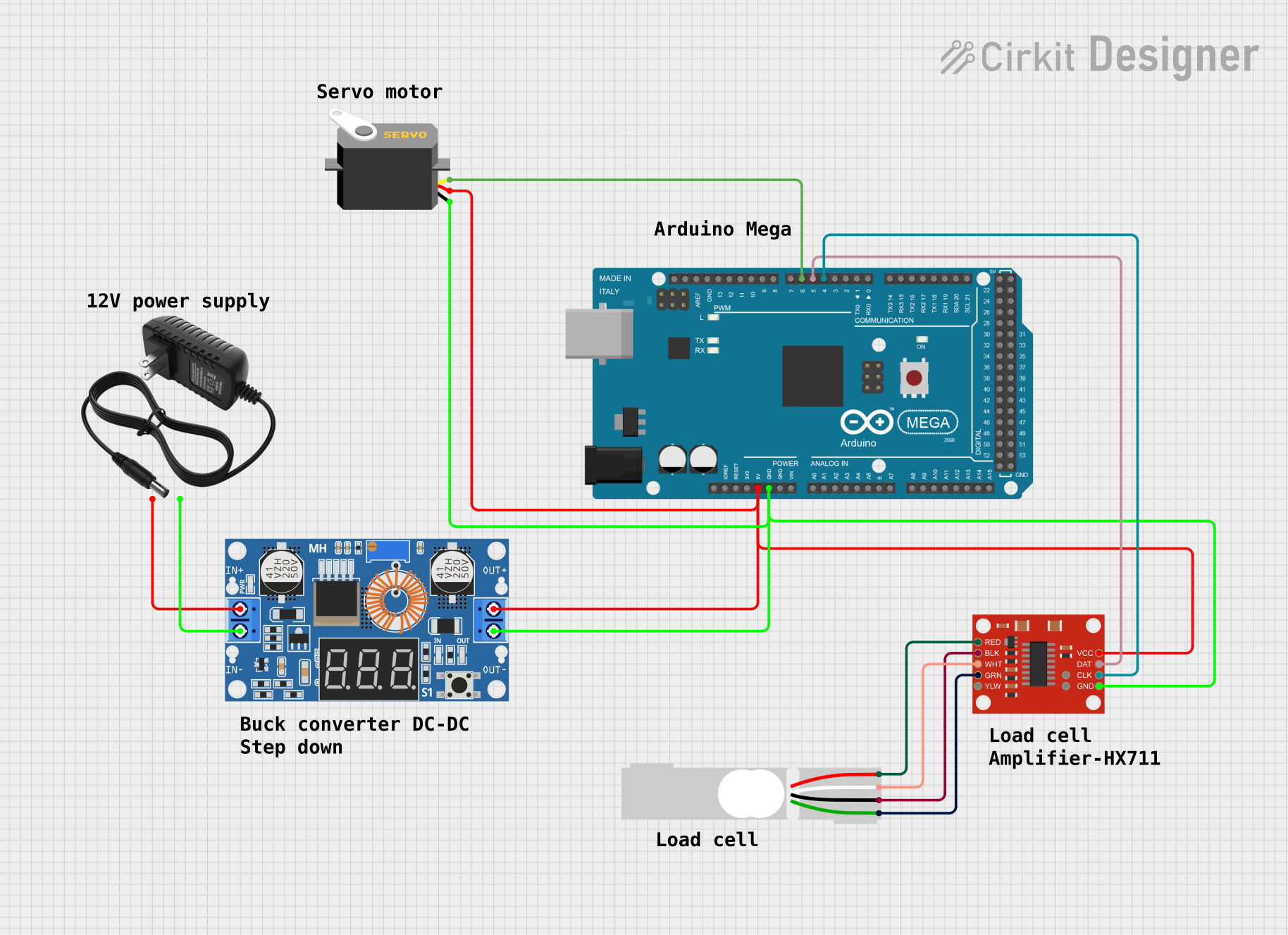
The NAU7802 is straightforward to use in load cell applications. Below are the steps and considerations for integrating it into a circuit:
Basic Circuit Connection:
- Power Supply: Connect AVDD and DVDD to a stable power source (2.7V to 5.5V). Connect AVSS and DVSS to ground.
- Load Cell Connection:
- Connect the load cell's positive and negative outputs to AIN1+ and AIN1-, respectively.
- If using a second load cell or differential input, connect it to AIN2+ and AIN2-.
- Reference Voltage: Use an external reference voltage source or connect VREFP and VREFN to AVDD and AVSS, respectively.
- I²C Communication: Connect the SDA and SCL pins to the corresponding I²C pins on your microcontroller. Use pull-up resistors (typically 4.7kΩ) on both lines.
- Data Ready Pin: Monitor the DRDY pin to know when data is ready for reading.
- Reset: Optionally, connect the RESET pin to the microcontroller for manual resets.
Important Considerations:
- Use decoupling capacitors (e.g., 0.1µF) near the power supply pins to reduce noise.
- Ensure proper grounding to avoid measurement errors.
- Configure the PGA gain based on the load cell's sensitivity and desired resolution.
- Use shielded cables for the load cell to minimize interference.
Example Code for Arduino UNO:
Below is an example of how to interface the NAU7802 with an Arduino UNO using the I²C protocol:
#include <Wire.h> // Include the Wire library for I²C communication

#define NAU7802_ADDRESS 0x2A // Default I²C address of the NAU7802
#define REG_PU_CTRL 0x00     // Power-up control register
#define REG_CTRL1 0x01       // Control register 1
#define REG_CTRL2 0x02       // Control register 2
#define REG_ADCO_B2 0x12     // ADC output MSB register

void setup() {
  Wire.begin(); // Initialize I²C communication
  Serial.begin(9600); // Initialize serial communication for debugging

  // Initialize the NAU7802
  nau7802Init();
}

void loop() {
  // Wait for data to be ready
  if (isDataReady()) {
    long adcValue = readADC(); // Read ADC value
    Serial.println(adcValue); // Print ADC value to the serial monitor
  }
  delay(100); // Small delay for stability
}

void nau7802Init() {
  writeRegister(REG_PU_CTRL, 0x30); // Power up the NAU7802
  delay(10); // Wait for the device to stabilize
  writeRegister(REG_CTRL1, 0x01); // Set PGA gain to 128
}

bool isDataReady() {
  Wire.beginTransmission(NAU7802_ADDRESS);
  Wire.write(REG_PU_CTRL);
  Wire.endTransmission();
  Wire.requestFrom(NAU7802_ADDRESS, 1);
  byte status = Wire.read();
  return (status & 0x01) == 0; // Check if DRDY bit is low
}

long readADC() {
  Wire.beginTransmission(NAU7802_ADDRESS);
  Wire.write(REG_ADCO_B2);
  Wire.endTransmission();
  Wire.requestFrom(NAU7802_ADDRESS, 3);

  // Combine the 3 bytes into a 24-bit signed integer
  long value = (long)Wire.read() << 16;
  value |= (long)Wire.read() << 8;
  value |= Wire.read();

  return value;
}

void writeRegister(byte reg, byte value) {
  Wire.beginTransmission(NAU7802_ADDRESS);
  Wire.write(reg);
  Wire.write(value);
  Wire.endTransmission();
}
Notes:
- The above code assumes the NAU7802 is using its default I²C address (0x2A).
- Adjust the PGA gain in
REG_CTRL1based on your load cell's requirements.
Troubleshooting and FAQs
Common Issues:
No Response from the NAU7802:
- Ensure the I²C connections (SDA, SCL) are correct and have pull-up resistors.
- Verify the power supply voltage is within the specified range.
Unstable or Noisy Readings:
- Check the grounding and shielding of the load cell wires.
- Use decoupling capacitors near the power pins.
- Ensure the reference voltage is stable.
Incorrect ADC Values:
- Verify the PGA gain setting matches the load cell's sensitivity.
- Check the load cell wiring for loose connections.
FAQs:
Can I use the NAU7802 with a 3.3V microcontroller? Yes, the NAU7802 operates with a supply voltage as low as 2.7V, making it compatible with 3.3V systems.
What is the maximum load cell capacity supported? The capacity depends on the load cell's sensitivity and the PGA gain setting. Ensure the output voltage remains within the ADC's input range.
Do I need an external oscillator? No, the NAU7802 has an integrated 2.5MHz oscillator. However, you can use an external crystal if needed for custom clock configurations.