Cirkit Designer Logo
Cirkit Designer
Your all-in-one circuit design IDE
Home / 
Component Documentation

How to Use USART: Examples, Pinouts, and Specs

Image of USART
Cirkit Designer LogoDesign with USART in Cirkit Designer

Introduction

The USART (Universal Synchronous Asynchronous Receiver Transmitter) is a communication interface module that enables microcontrollers to communicate with peripheral devices and other microcontrollers through serial communication, both synchronously and asynchronously. It is widely used in embedded systems for serial data exchange with devices such as sensors, memory, and other microcontrollers or computers.

Explore Projects Built with USART

Use Cirkit Designer to design, explore, and prototype these projects online. Some projects support real-time simulation. Click "Open Project" to start designing instantly!
ESP32 and Arduino UNO Serial Communication Interface
Image of ESP32 Arduino COM SErial: A project utilizing USART in a practical application
This circuit integrates an ESP32 Wroom Dev Kit and an Arduino UNO, connected via their TXD/RXD pins for serial communication and sharing a common ground. Both microcontrollers are programmed with basic setup and loop functions, indicating a potential for further development of communication or control tasks.
Cirkit Designer LogoOpen Project in Cirkit Designer
Arduino UNO and Relay-Controlled RS485 Communication System
Image of Diagrama: A project utilizing USART in a practical application
This circuit features an Arduino UNO microcontroller interfaced with a 4-channel relay module and a UART TTL to RS485 converter. The Arduino controls the relays via digital pins and communicates with the RS485 converter for serial communication, enabling control of external devices and communication over long distances.
Cirkit Designer LogoOpen Project in Cirkit Designer
Arduino UNO and MAX 3232 Module Controlled NE-1000 Pump System
Image of NE-1000 RS232: A project utilizing USART in a practical application
This circuit features an Arduino UNO microcontroller interfaced with a MAX 3232 module for serial communication. The Arduino provides power and ground to the MAX 3232, and the two devices communicate via the TxD and RxD pins. The setup is likely intended for serial data transmission between the Arduino and another device.
Cirkit Designer LogoOpen Project in Cirkit Designer
Arduino Mega 2560-Controlled Servo System with Bluetooth and Sensor Interface
Image of Završni: A project utilizing USART in a practical application
This is a microcontroller-based control system featuring an Arduino Mega 2560, designed to receive inputs from a rotary potentiometer, push switches, and an IR sensor, and to drive multiple servos and an LCD display. It includes an HC-05 Bluetooth module for wireless communication, allowing for remote interfacing and control.
Cirkit Designer LogoOpen Project in Cirkit Designer

Explore Projects Built with USART

Use Cirkit Designer to design, explore, and prototype these projects online. Some projects support real-time simulation. Click "Open Project" to start designing instantly!
Image of ESP32 Arduino COM SErial: A project utilizing USART in a practical application
ESP32 and Arduino UNO Serial Communication Interface
This circuit integrates an ESP32 Wroom Dev Kit and an Arduino UNO, connected via their TXD/RXD pins for serial communication and sharing a common ground. Both microcontrollers are programmed with basic setup and loop functions, indicating a potential for further development of communication or control tasks.
Cirkit Designer LogoOpen Project in Cirkit Designer
Image of Diagrama: A project utilizing USART in a practical application
Arduino UNO and Relay-Controlled RS485 Communication System
This circuit features an Arduino UNO microcontroller interfaced with a 4-channel relay module and a UART TTL to RS485 converter. The Arduino controls the relays via digital pins and communicates with the RS485 converter for serial communication, enabling control of external devices and communication over long distances.
Cirkit Designer LogoOpen Project in Cirkit Designer
Image of NE-1000 RS232: A project utilizing USART in a practical application
Arduino UNO and MAX 3232 Module Controlled NE-1000 Pump System
This circuit features an Arduino UNO microcontroller interfaced with a MAX 3232 module for serial communication. The Arduino provides power and ground to the MAX 3232, and the two devices communicate via the TxD and RxD pins. The setup is likely intended for serial data transmission between the Arduino and another device.
Cirkit Designer LogoOpen Project in Cirkit Designer
Image of Završni: A project utilizing USART in a practical application
Arduino Mega 2560-Controlled Servo System with Bluetooth and Sensor Interface
This is a microcontroller-based control system featuring an Arduino Mega 2560, designed to receive inputs from a rotary potentiometer, push switches, and an IR sensor, and to drive multiple servos and an LCD display. It includes an HC-05 Bluetooth module for wireless communication, allowing for remote interfacing and control.
Cirkit Designer LogoOpen Project in Cirkit Designer

Common Applications and Use Cases

  • Serial communication with peripheral devices
  • Data exchange between microcontrollers
  • Interface for Bluetooth modules
  • GPS module data reception
  • Debugging and logging purposes

Technical Specifications

Key Technical Details

  • Operating Voltage: Typically 3.3V or 5V (varies by microcontroller)
  • Data Bits: 5 to 9 bits
  • Stop Bits: 1 or 2 bits
  • Parity: None, Even, or Odd
  • Baud Rate: Configurable, up to several Mbps
  • Communication Modes: Full-duplex, half-duplex, simplex
  • Error Detection: Framing, parity, and overrun error detection

Pin Configuration and Descriptions

Pin Name Description
TX Transmit pin, sends serial data to peripheral devices
RX Receive pin, receives serial data from peripheral devices
CTS Clear To Send, optional hardware flow control input pin
RTS Request To Send, optional hardware flow control output pin
GND Ground, reference voltage for the USART signals

Usage Instructions

How to Use the Component in a Circuit

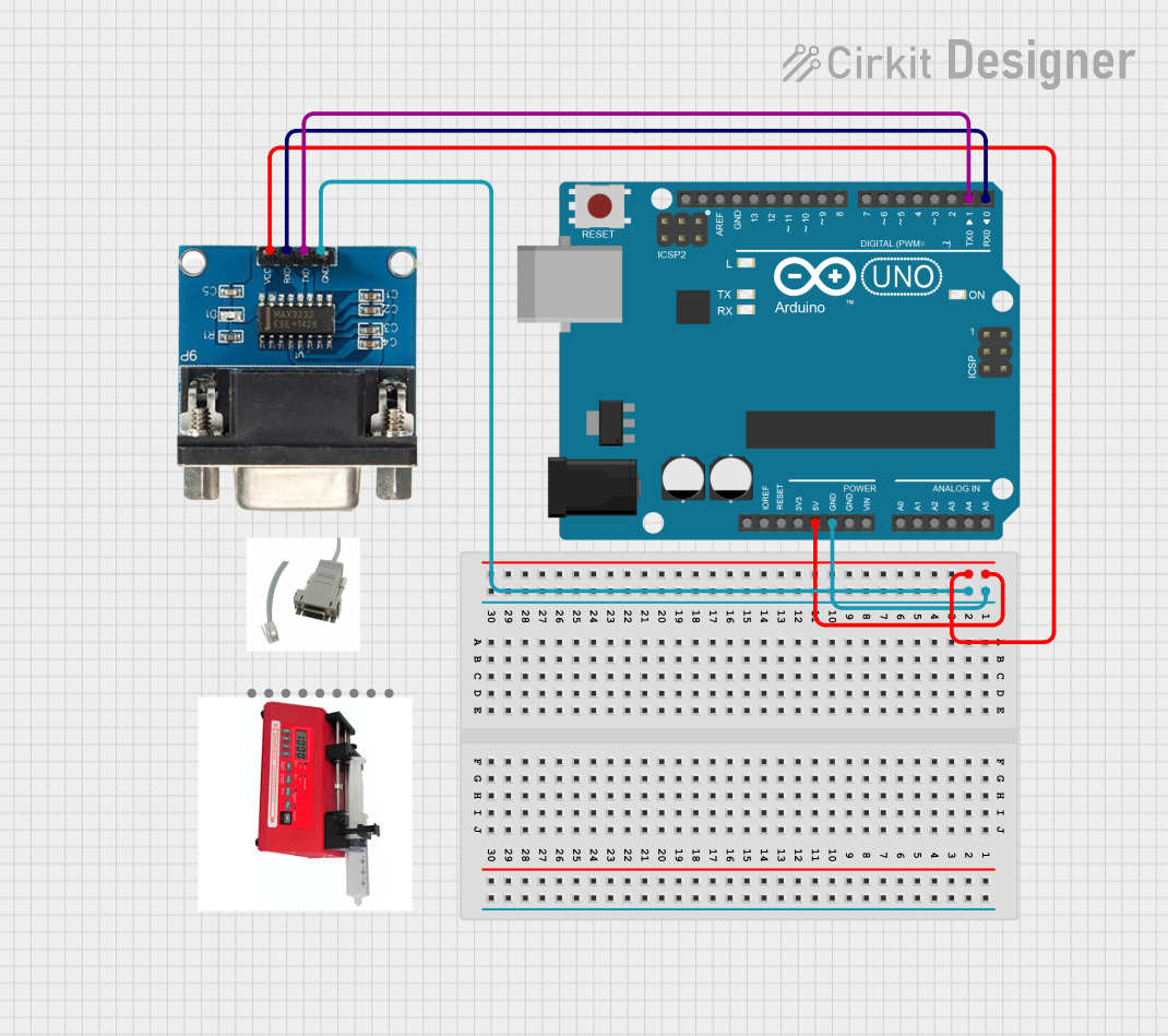
  1. Power Supply: Connect the VCC pin to the appropriate voltage level (3.3V or 5V) and GND to the ground.
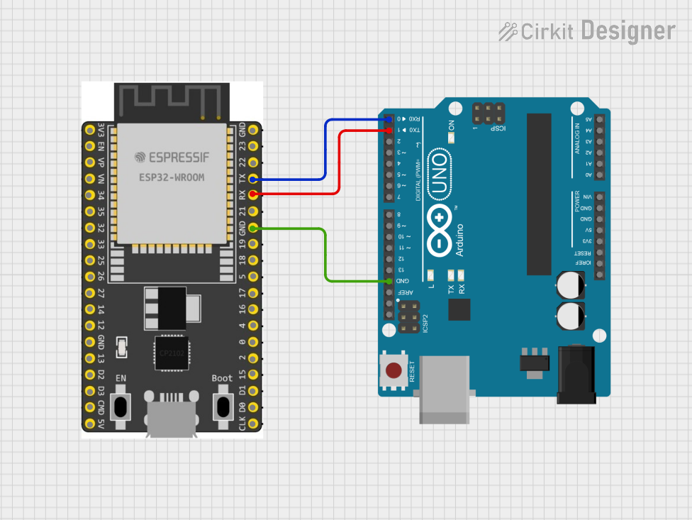
  2. Connecting TX/RX: Connect the TX pin to the RX pin of the peripheral device and vice versa.
  3. Flow Control (Optional): If hardware flow control is used, connect the CTS and RTS pins accordingly.
  4. Configuration: Configure the USART settings (baud rate, data bits, parity, stop bits) to match the peripheral device.

Important Considerations and Best Practices

  • Ensure that the baud rate of the USART matches the baud rate of the peripheral device.
  • Use proper level shifting if the operating voltage between the microcontroller and peripheral differs.
  • Avoid long wires at high baud rates to minimize noise and signal degradation.
  • Implement error checking in software to handle communication errors.

Troubleshooting and FAQs

Common Issues Users Might Face

  • Data Corruption: This can be due to incorrect baud rate settings or noise on the communication lines.
  • No Communication: Ensure that the TX and RX pins are not swapped and that the device is powered correctly.

Solutions and Tips for Troubleshooting

  • Double-check the USART configuration settings.
  • Use an oscilloscope to verify the signal integrity on the TX and RX lines.
  • Implement a timeout mechanism in software to recover from communication errors.

FAQs

  • Q: Can USART be used for both synchronous and asynchronous communication? A: Yes, USART can be configured for either mode depending on the application requirements.

  • Q: What is the maximum distance for reliable USART communication? A: It depends on the baud rate and the quality of the cables, but it is generally recommended to keep the distance short, typically less than a few meters.

Example Code for Arduino UNO

#include <SoftwareSerial.h>

// Create a software serial object
SoftwareSerial mySerial(10, 11); // RX, TX

void setup() {
  // Open serial communications and wait for port to open:
  Serial.begin(9600);
  while (!Serial) {
    ; // Wait for serial port to connect. Needed for native USB port only
  }

  // Set the data rate for the SoftwareSerial port
  mySerial.begin(4800);
}

void loop() { // run over and over
  if (mySerial.available()) {
    Serial.write(mySerial.read());
  }
  if (Serial.available()) {
    mySerial.write(Serial.read());
  }
}

Note: This example uses SoftwareSerial library to emulate a serial port on digital pins 10 and 11. For hardware USART, refer to the specific microcontroller's datasheet for register configuration.

Disclaimer: The part ID TJC8048x270_001R provided does not correspond to a known USART component and is used here for illustrative purposes only. Always refer to the manufacturer's datasheet for accurate specifications and pin configurations.