How to Use Arduino Mega ADK (Rev3): Examples, Pinouts, and Specs
Introduction
The Arduino Mega ADK (Rev3) is a microcontroller board based on the ATmega2560, designed for building complex projects and prototypes, particularly those that interact with Android devices. It features a USB host interface, which allows it to communicate with Android phones and tablets, making it ideal for developers looking to create Android accessories. The board is also compatible with numerous shields, expanding its capabilities for various applications such as robotics, home automation, and IoT projects.
Explore Projects Built with Arduino Mega ADK (Rev3)
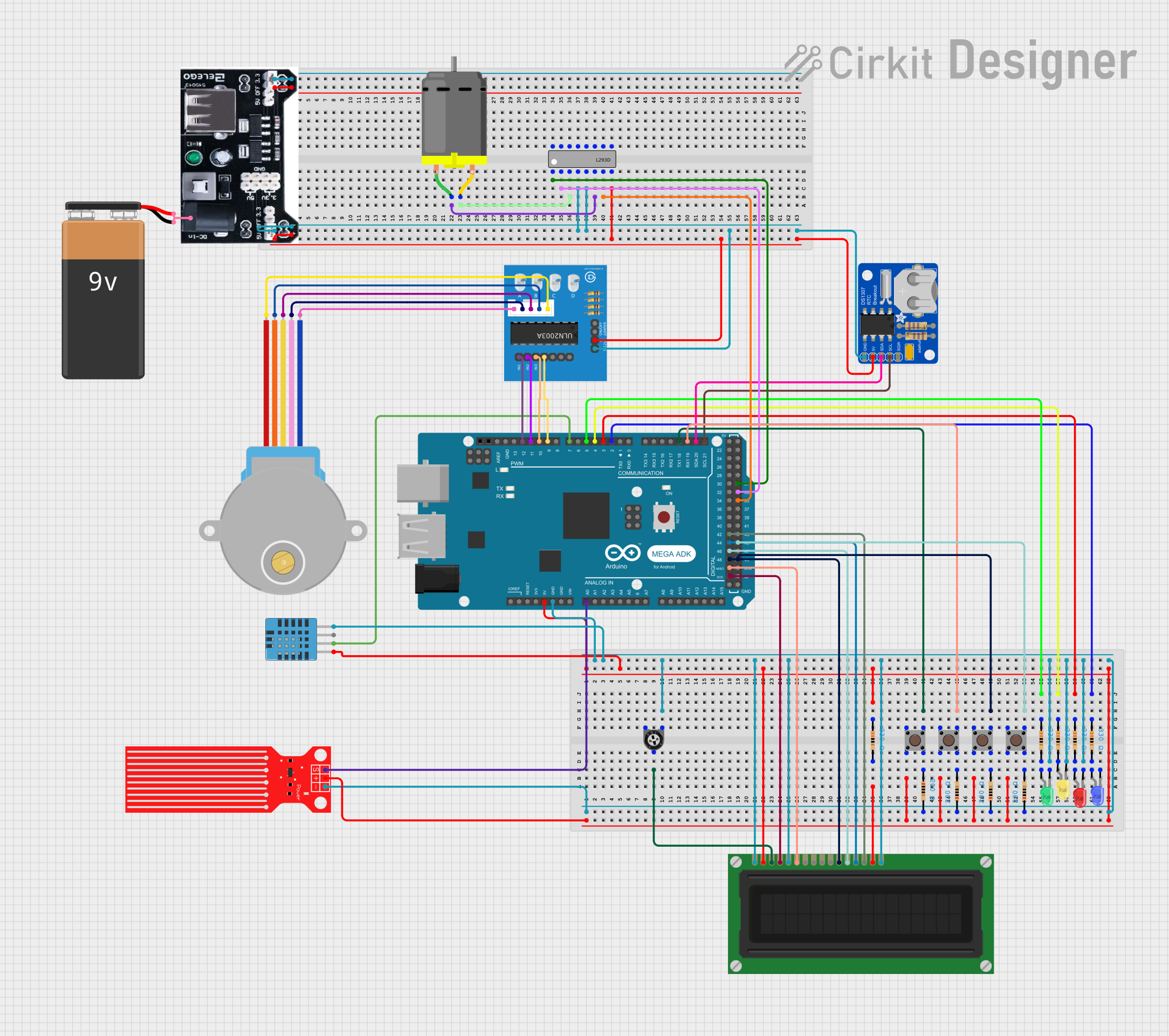
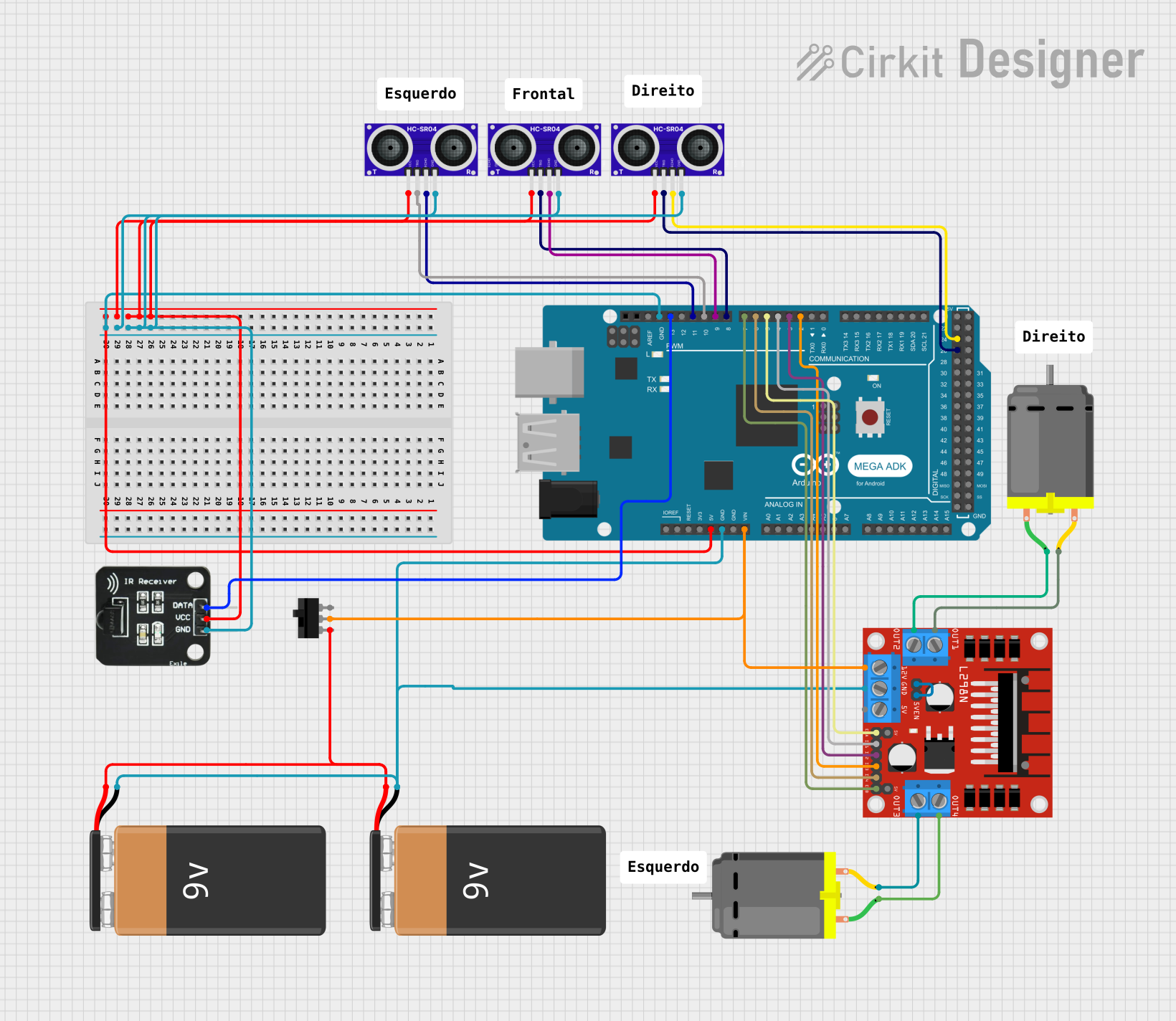
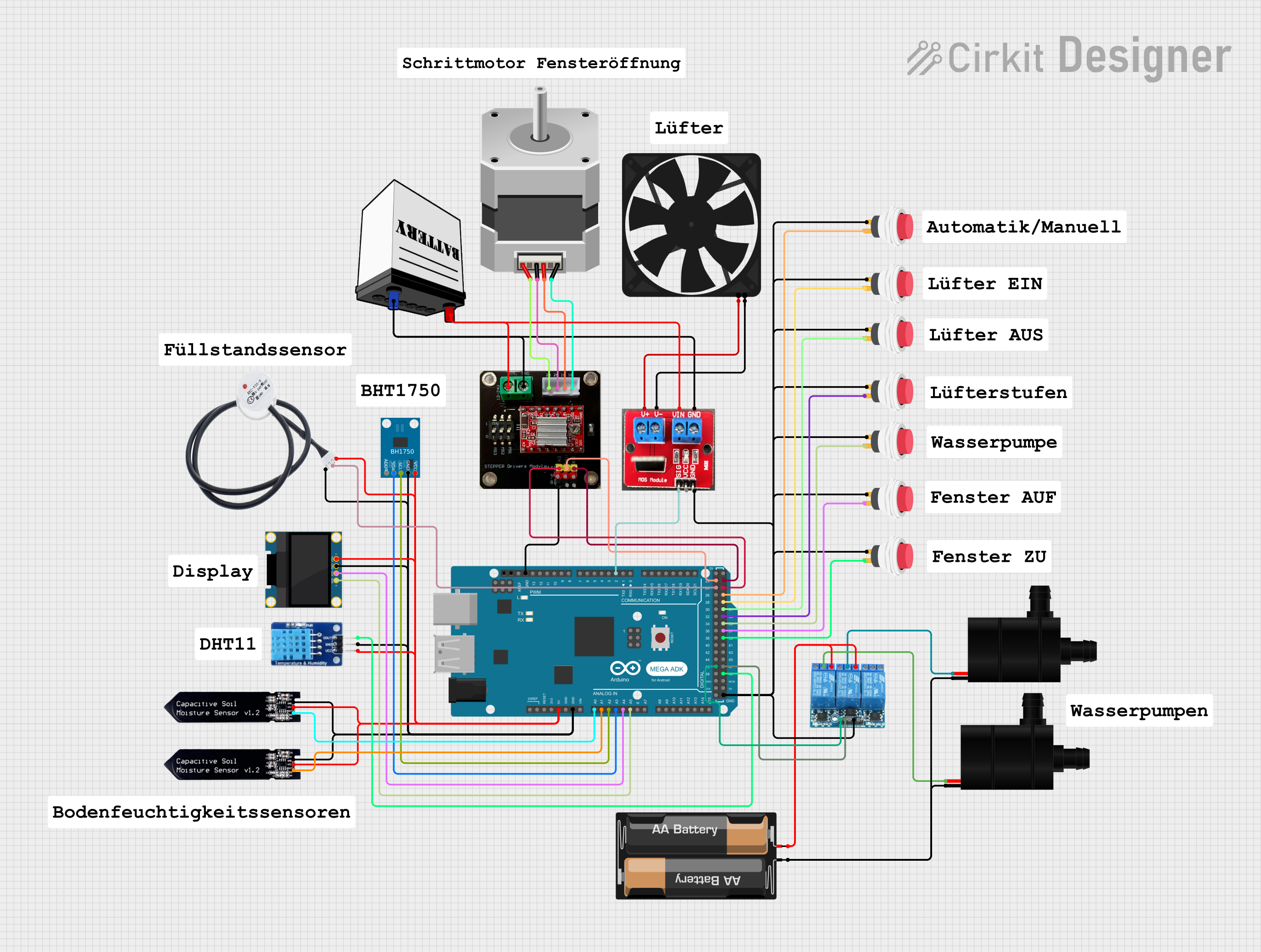
Explore Projects Built with Arduino Mega ADK (Rev3)
Technical Specifications
Key Technical Details
- Microcontroller: ATmega2560
- Operating Voltage: 5V
- Input Voltage (recommended): 7-12V
- Input Voltage (limits): 6-20V
- Digital I/O Pins: 54 (of which 15 provide PWM output)
- Analog Input Pins: 16
- DC Current per I/O Pin: 40 mA
- DC Current for 3.3V Pin: 50 mA
- Flash Memory: 256 KB of which 8 KB used by bootloader
- SRAM: 8 KB
- EEPROM: 4 KB
- Clock Speed: 16 MHz
- USB Host: Yes (MAX3421E)
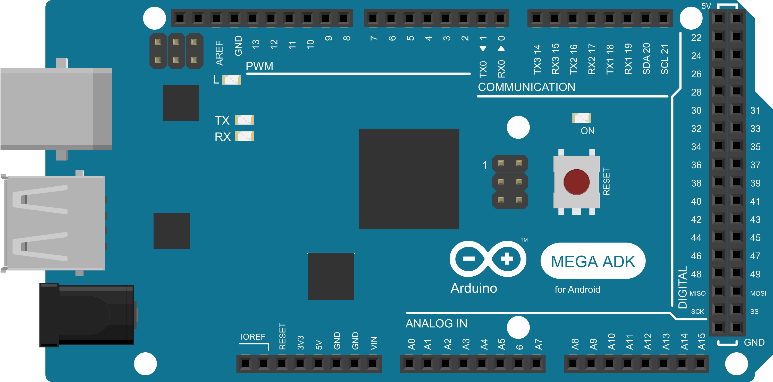
Pin Configuration and Descriptions
| Pin Number | Function | Description |
|---|---|---|
| 1-54 | Digital I/O | Digital pins, PWM available on pins 2 to 13, 44 to 46 |
| A0-A15 | Analog Input | Analog input pins |
| GND | Ground | Ground pins |
| 5V | Power | 5V power supply |
| 3.3V | Power | 3.3V power supply |
| VIN | Voltage Input | Input voltage for the board when using an external power source |
| RESET | Reset | Resets the microcontroller |
| ICSP | In-Circuit Serial Programming | Used for bootloader flashing and direct programming |
Usage Instructions
Integrating with a Circuit
Powering the Board: The Arduino Mega ADK can be powered via the USB connection or with an external power supply. The power source is selected automatically.
Connecting to Android Devices: Use a USB cable to connect the board's USB host to the Android device. Ensure your Android device supports USB OTG.
Programming the Board: Connect the board to your computer using a USB cable. Select the correct board and port in the Arduino IDE, and upload your sketch.
Using Digital I/O Pins: Configure the pins as INPUT or OUTPUT using the
pinMode()function. UsedigitalWrite()to set an OUTPUT to HIGH or LOW, anddigitalRead()to read the state of an INPUT.Using Analog Input Pins: Read analog voltages using the
analogRead()function. The board operates at 5V, which means that 5V corresponds to ananalogRead()value of 1023.Using PWM Pins: Generate a PWM signal using
analogWrite()on the PWM-enabled digital pins.
Best Practices
- Always disconnect the board from the power source before making any changes to the circuit.
- Use a current limiting resistor when connecting LEDs to digital pins.
- Avoid powering high-current devices directly from the board's pins; use external power sources and transistors or relays instead.
Example Code for Arduino UNO
// Example sketch for Arduino Mega ADK (Rev3) to blink an LED

const int ledPin = 13; // LED connected to digital pin 13

void setup() {
  pinMode(ledPin, OUTPUT); // Initialize the digital pin as an output
}

void loop() {
  digitalWrite(ledPin, HIGH); // Turn the LED on
  delay(1000);                // Wait for a second
  digitalWrite(ledPin, LOW);  // Turn the LED off
  delay(1000);                // Wait for a second
}
Troubleshooting and FAQs
Common Issues
- Android Device Not Recognizing the Board: Ensure the Android device supports USB OTG and that you're using a compatible USB cable.
- Sketch Not Uploading: Check the selected board and port in the Arduino IDE. Ensure the correct drivers are installed.
- Insufficient Power: If using servos or motors, ensure the board has an adequate external power supply.
FAQs
Q: Can I use the Arduino Mega ADK for non-Android projects? A: Yes, the board functions as a regular Arduino Mega when not using the USB host feature.
Q: What is the purpose of the ICSP header? A: The ICSP header allows you to program the microcontroller directly with an external programmer.
Q: How do I connect multiple shields to the board? A: Ensure the shields are stackable and compatible with the Mega's pin layout. Stack them carefully, aligning the pins correctly.
For further assistance, consult the Arduino community forums or the extensive online resources available for the Arduino Mega ADK.