
How to Use Function Generator: Examples, Pinouts, and Specs
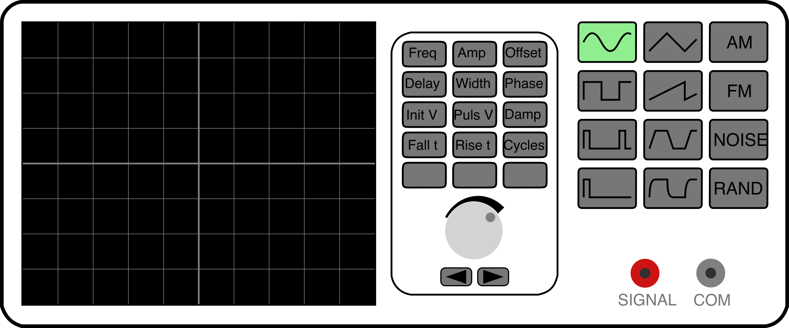
 Design with Function Generator in Cirkit Designer
Introduction
A function generator is a versatile electronic device that produces various types of electrical waveforms, such as sine, square, triangular, and sawtooth waves, over a wide range of frequencies. It is commonly used in the testing, troubleshooting, and design of electronic circuits. Function generators are essential tools in laboratories, educational environments, and industries for simulating signals and analyzing circuit behavior.
Explore Projects Built with Function Generator
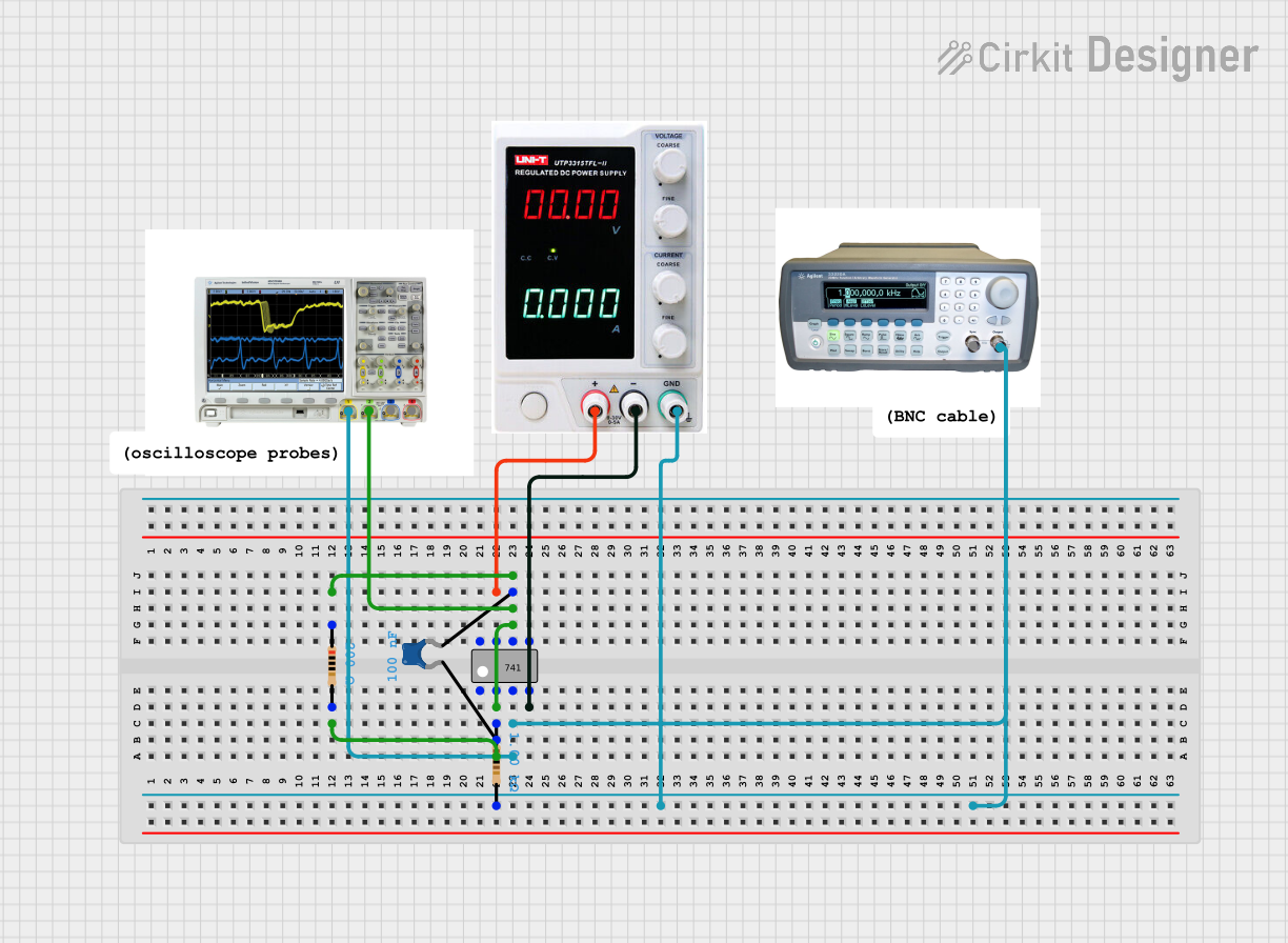 Open Project in Cirkit Designer
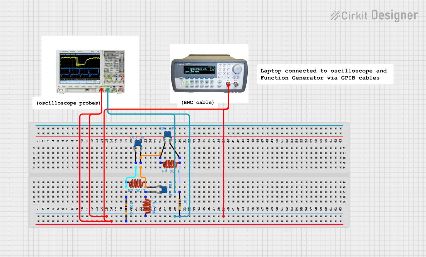 Open Project in Cirkit Designer
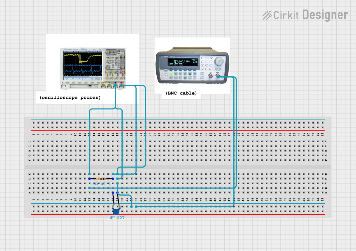 Open Project in Cirkit Designer
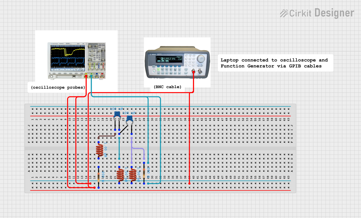 Open Project in Cirkit Designer
Explore Projects Built with Function Generator
Open Project in Cirkit DesignerOpen Project in Cirkit DesignerOpen Project in Cirkit DesignerOpen Project in Cirkit DesignerCommon Applications and Use Cases
- Testing and debugging electronic circuits
- Simulating sensor signals for microcontroller projects
- Frequency response analysis of amplifiers and filters
- Generating clock signals for digital circuits
- Educational demonstrations in electronics and signal processing
Technical Specifications
Below are the typical technical specifications of a function generator. Note that actual values may vary depending on the specific model.
General Specifications
- Frequency Range: 0.1 Hz to 10 MHz (varies by model)
- Waveform Types: Sine, Square, Triangle, Sawtooth, Pulse
- Amplitude Range: 0.1 Vpp to 20 Vpp (peak-to-peak voltage)
- Output Impedance: 50 Ω (typical)
- Frequency Accuracy: ±0.1% of the set value
- Power Supply: 110-240V AC or external DC (varies by model)
Pin Configuration and Descriptions
The output and control interface of a function generator typically include the following:
| Pin/Port | Description |
|---|---|
| Output (BNC) | Main signal output port for connecting to the circuit under test. |
| Sync Out (optional) | Provides a synchronization signal for triggering oscilloscopes or other devices. |
| Frequency Knob | Adjusts the frequency of the output waveform. |
| Amplitude Knob | Controls the amplitude (voltage level) of the output waveform. |
| Waveform Selector | Switch or button to select the desired waveform type (sine, square, etc.). |
| Offset Control | Adds a DC offset to the output waveform. |
| Power Input | Connects to the power source (AC or DC, depending on the model). |
Usage Instructions
How to Use the Function Generator in a Circuit
- Power On the Device: Connect the function generator to a power source and turn it on.
- Select the Waveform: Use the waveform selector to choose the desired waveform type (e.g., sine, square, triangle).
- Set the Frequency: Adjust the frequency knob to set the desired frequency for the output signal.
- Adjust the Amplitude: Use the amplitude knob to set the peak-to-peak voltage of the waveform.
- Connect to the Circuit: Use a BNC cable or probe to connect the output port of the function generator to the input of the circuit under test.
- Optional - Add DC Offset: If required, adjust the offset control to add a DC bias to the waveform.
- Monitor the Output: Use an oscilloscope to verify the waveform and ensure it meets the desired parameters.
Important Considerations and Best Practices
- Load Impedance: Ensure the circuit's input impedance matches the function generator's output impedance (typically 50 Ω) to avoid signal distortion.
- Voltage Limits: Do not exceed the voltage rating of the circuit under test to prevent damage.
- Grounding: Ensure proper grounding to avoid noise or interference in the signal.
- Frequency Range: Verify that the selected frequency is within the operating range of the circuit under test.
- Use an Oscilloscope: Always monitor the output waveform with an oscilloscope to confirm its accuracy.
Example: Using a Function Generator with an Arduino UNO
A function generator can be used to simulate an analog input signal for an Arduino UNO. Below is an example of Arduino code to read and display the signal's frequency.
// Arduino code to measure the frequency of a signal
// Connect the function generator output to pin 2 of the Arduino UNO

const int signalPin = 2; // Pin connected to the function generator output
volatile unsigned long pulseCount = 0; // Counter for signal pulses

void setup() {
  pinMode(signalPin, INPUT); // Set the signal pin as input
  Serial.begin(9600); // Initialize serial communication
  attachInterrupt(digitalPinToInterrupt(signalPin), countPulse, RISING);
  // Attach an interrupt to count pulses on the rising edge
}

void loop() {
  delay(1000); // Wait for 1 second
  noInterrupts(); // Temporarily disable interrupts
  unsigned long frequency = pulseCount; // Copy pulse count
  pulseCount = 0; // Reset pulse count
  interrupts(); // Re-enable interrupts

  Serial.print("Frequency: ");
  Serial.print(frequency);
  Serial.println(" Hz");
}

// Interrupt service routine to count pulses
void countPulse() {
  pulseCount++;
}
Troubleshooting and FAQs
Common Issues and Solutions
No Output Signal
- Cause: The function generator may not be powered on or configured correctly.
- Solution: Check the power connection, ensure the device is turned on, and verify the waveform, frequency, and amplitude settings.
Distorted Waveform
- Cause: Impedance mismatch or incorrect amplitude settings.
- Solution: Ensure the circuit's input impedance matches the function generator's output impedance. Adjust the amplitude to an appropriate level.
Signal Not Detected by Circuit
- Cause: Loose connections or incorrect frequency range.
- Solution: Verify all connections and ensure the frequency is within the circuit's operating range.
Oscilloscope Shows Noise
- Cause: Poor grounding or external interference.
- Solution: Check the grounding of the function generator and circuit. Minimize external noise sources.
FAQs
Can I use a function generator to power a circuit?
- No, function generators are designed to provide low-power signals for testing purposes, not to power circuits.
What is the difference between a function generator and a signal generator?
- A function generator produces standard waveforms (sine, square, triangle, etc.), while a signal generator is typically used for more specialized signals, such as modulated RF signals.
How do I generate a pulse waveform?
- Use the waveform selector to choose the pulse waveform and adjust the duty cycle and frequency as needed.
Can I connect a function generator directly to a microcontroller?
- Yes, but ensure the signal voltage levels are within the microcontroller's input voltage range to avoid damage.
By following this documentation, users can effectively utilize a function generator for various applications and troubleshoot common issues.