
How to Use LM2621: Examples, Pinouts, and Specs

 Design with LM2621 in Cirkit Designer
Introduction
The LM2621 is a high-efficiency, step-down (buck) voltage regulator capable of delivering up to 1A of output current. It operates over a wide input voltage range of 2V to 14V, making it versatile for various power supply applications. With its low quiescent current, the LM2621 is particularly well-suited for battery-powered devices, where energy efficiency is critical. Additionally, the device includes built-in protection features such as thermal shutdown and current limiting, ensuring reliable operation under demanding conditions.
Explore Projects Built with LM2621
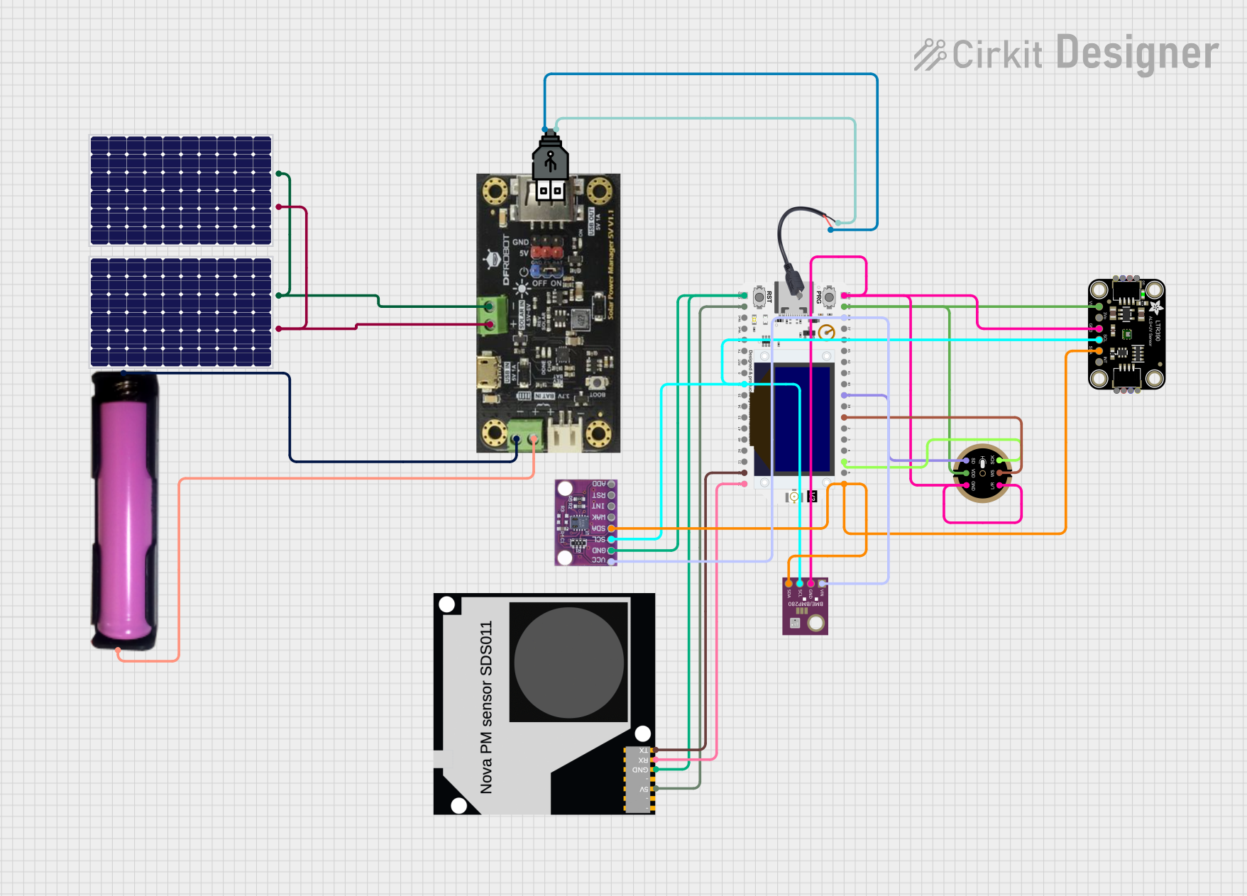 Open Project in Cirkit Designer
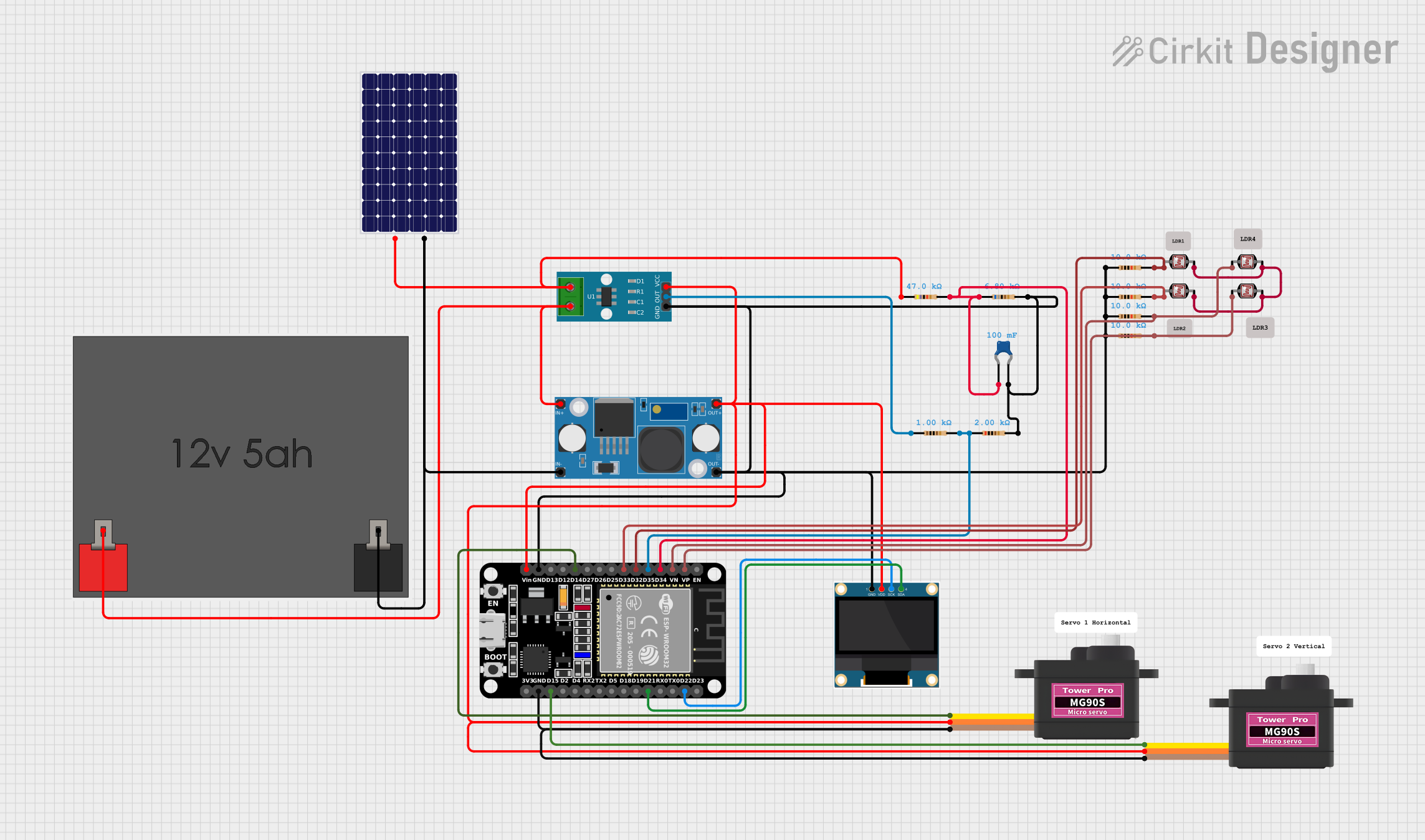 Open Project in Cirkit Designer
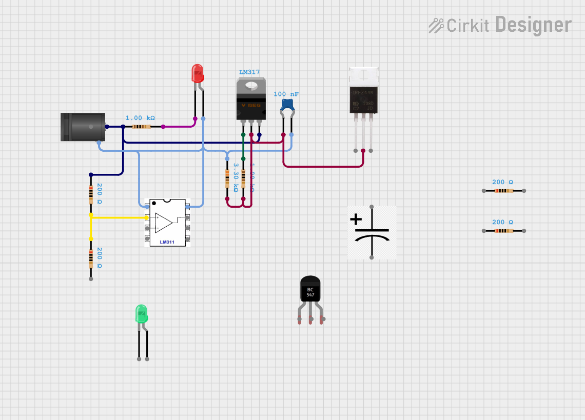 Open Project in Cirkit Designer
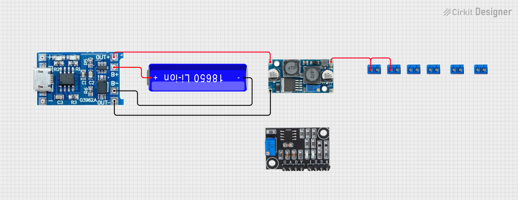 Open Project in Cirkit Designer
Explore Projects Built with LM2621
Open Project in Cirkit DesignerOpen Project in Cirkit DesignerOpen Project in Cirkit DesignerOpen Project in Cirkit DesignerCommon Applications
- Portable and battery-powered devices
- Point-of-load power supplies
- Industrial and automotive electronics
- Consumer electronics (e.g., smartphones, tablets, and wearables)
Technical Specifications
Key Specifications
| Parameter | Value |
|---|---|
| Input Voltage Range | 2V to 14V |
| Output Voltage Range | Adjustable (0.8V to 12V) |
| Maximum Output Current | 1A |
| Switching Frequency | 600kHz to 1.5MHz (adjustable) |
| Efficiency | Up to 90% |
| Quiescent Current | 1.5mA (typical) |
| Shutdown Current | 0.1µA (typical) |
| Operating Temperature Range | -40°C to +125°C |
Pin Configuration and Descriptions
The LM2621 is typically available in an 8-pin SOIC or MSOP package. Below is the pinout and description:
| Pin Number | Pin Name | Description |
|---|---|---|
| 1 | SW | Switch node. Connect to the inductor and diode. |
| 2 | GND | Ground. Connect to the system ground. |
| 3 | FB | Feedback input. Connect to a resistor divider to set the output voltage. |
| 4 | SHDN | Shutdown pin. Pull low to disable the regulator; pull high to enable it. |
| 5 | VIN | Input voltage supply. Connect to the input power source. |
| 6 | COMP | Compensation pin. Connect a capacitor to stabilize the control loop. |
| 7 | NC | No connection. Leave this pin unconnected. |
| 8 | VOUT | Output voltage. Connect to the load and output capacitor. |
Usage Instructions
How to Use the LM2621 in a Circuit
Input and Output Capacitors:
- Place a low-ESR ceramic capacitor (e.g., 10µF) close to the VIN pin to filter input noise.
- Use a similar capacitor (e.g., 22µF) at the output to stabilize the voltage and reduce ripple.
Inductor Selection:
- Choose an inductor with a current rating higher than the maximum output current (1A).
- The inductance value typically ranges from 4.7µH to 22µH, depending on the desired ripple current.
Feedback Resistor Divider:
- Use two resistors to set the output voltage. The formula is: [ V_{OUT} = V_{REF} \times \left(1 + \frac{R1}{R2}\right) ] where ( V_{REF} ) is 0.8V (internal reference voltage).
Compensation:
- Connect a capacitor (e.g., 1nF to 10nF) to the COMP pin to stabilize the control loop.
Enable/Disable:
- Pull the SHDN pin high (above 1.6V) to enable the regulator.
- Pull it low (below 0.4V) to disable the regulator and reduce power consumption.
Example Circuit with Arduino UNO
The LM2621 can be used to power an Arduino UNO from a higher voltage source (e.g., a 12V battery). Below is an example circuit and Arduino code to monitor the output voltage.
Circuit Diagram
- Connect the LM2621 as follows:
- VIN: 12V battery
- VOUT: 5V (set using the feedback resistor divider)
- GND: Common ground
- SHDN: Connected to a digital pin on the Arduino for control
Arduino Code
// LM2621 Output Voltage Monitoring and Control
const int shdnPin = 7;  // Pin connected to SHDN pin of LM2621
const int voutPin = A0; // Analog pin to read output voltage

void setup() {
  pinMode(shdnPin, OUTPUT); // Set SHDN pin as output
  digitalWrite(shdnPin, HIGH); // Enable the LM2621 regulator

  Serial.begin(9600); // Initialize serial communication
}

void loop() {
  // Read the output voltage (scaled by a resistor divider)
  int analogValue = analogRead(voutPin);

  // Convert the analog reading to voltage (assuming 10-bit ADC and 5V reference)
  float outputVoltage = (analogValue / 1023.0) * 5.0 * 2;
  // Multiply by 2 if a 1:1 resistor divider is used

  // Print the output voltage to the serial monitor
  Serial.print("Output Voltage: ");
  Serial.print(outputVoltage);
  Serial.println(" V");

  delay(1000); // Wait for 1 second before the next reading
}
Important Considerations
- Thermal Management: Ensure adequate heat dissipation, especially at high currents. Use a PCB with good thermal conductivity or add a heatsink if necessary.
- Input Voltage Range: Do not exceed the maximum input voltage of 14V to avoid damaging the device.
- Output Ripple: Minimize output ripple by using low-ESR capacitors and proper PCB layout techniques.
Troubleshooting and FAQs
Common Issues and Solutions
No Output Voltage:
- Check if the SHDN pin is pulled high to enable the regulator.
- Verify the input voltage is within the specified range (2V to 14V).
- Inspect the feedback resistor divider for correct values.
Excessive Output Ripple:
- Use low-ESR capacitors at the input and output.
- Ensure the inductor value is appropriate for the desired ripple current.
Overheating:
- Verify that the load current does not exceed 1A.
- Improve thermal dissipation by using a larger PCB area for the GND plane.
Device Not Switching:
- Check the COMP pin capacitor for proper value and connection.
- Ensure the switching frequency is set correctly (if adjustable).
FAQs
Q: Can the LM2621 be used for negative output voltages?
A: No, the LM2621 is designed for step-down (buck) operation and cannot generate negative voltages.
Q: What happens if the input voltage drops below 2V?
A: The regulator will stop operating, and the output voltage will drop. Ensure the input voltage remains within the specified range.
Q: Can I use the LM2621 for applications requiring more than 1A?
A: No, the LM2621 is rated for a maximum output current of 1A. For higher currents, consider using a different regulator with a higher current rating.
Q: How do I calculate the efficiency of the LM2621?
A: Efficiency can be calculated as:
[
\text{Efficiency} = \left(\frac{V_{OUT} \times I_{OUT}}{V_{IN} \times I_{IN}}\right) \times 100%
]
Measure ( V_{IN} ), ( V_{OUT} ), ( I_{IN} ), and ( I_{OUT} ) to determine efficiency.
This concludes the LM2621 documentation.