How to Use LED matrix_small: Examples, Pinouts, and Specs

 Design with LED matrix_small in Cirkit Designer
Introduction
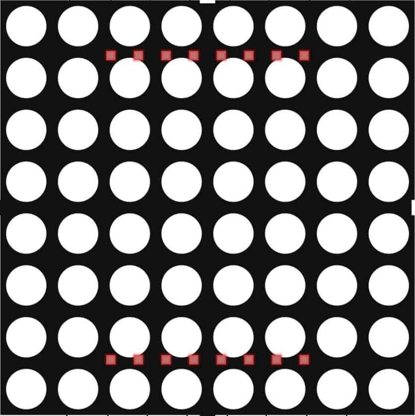
A small LED matrix is an array of light-emitting diodes (LEDs) arranged in a grid, typically in configurations such as 8x8, 5x7, or 16x16. Each LED in the matrix can be individually controlled to display text, images, or patterns. These matrices are widely used in electronic projects for creating visual displays, such as scrolling text, animations, or simple indicators.
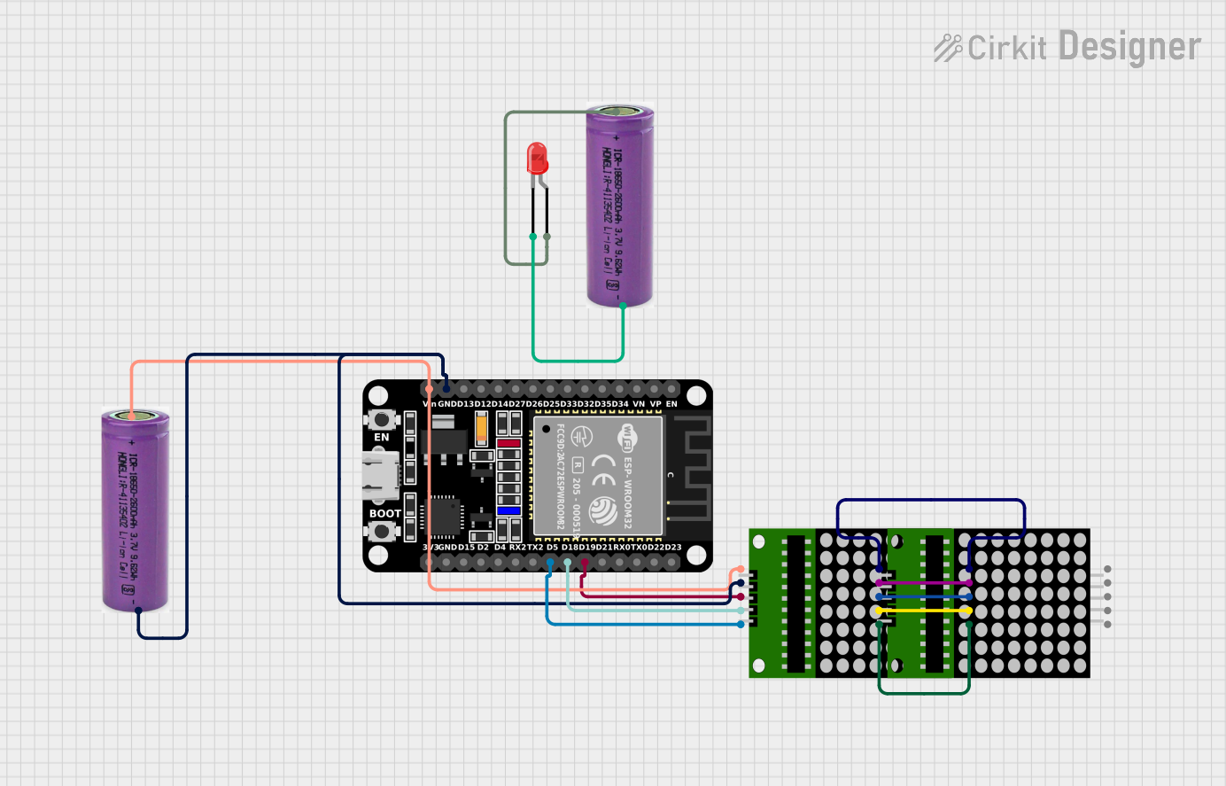
Explore Projects Built with LED matrix_small

 Open Project in Cirkit Designer
 Open Project in Cirkit Designer
 Open Project in Cirkit Designer
 Open Project in Cirkit Designer
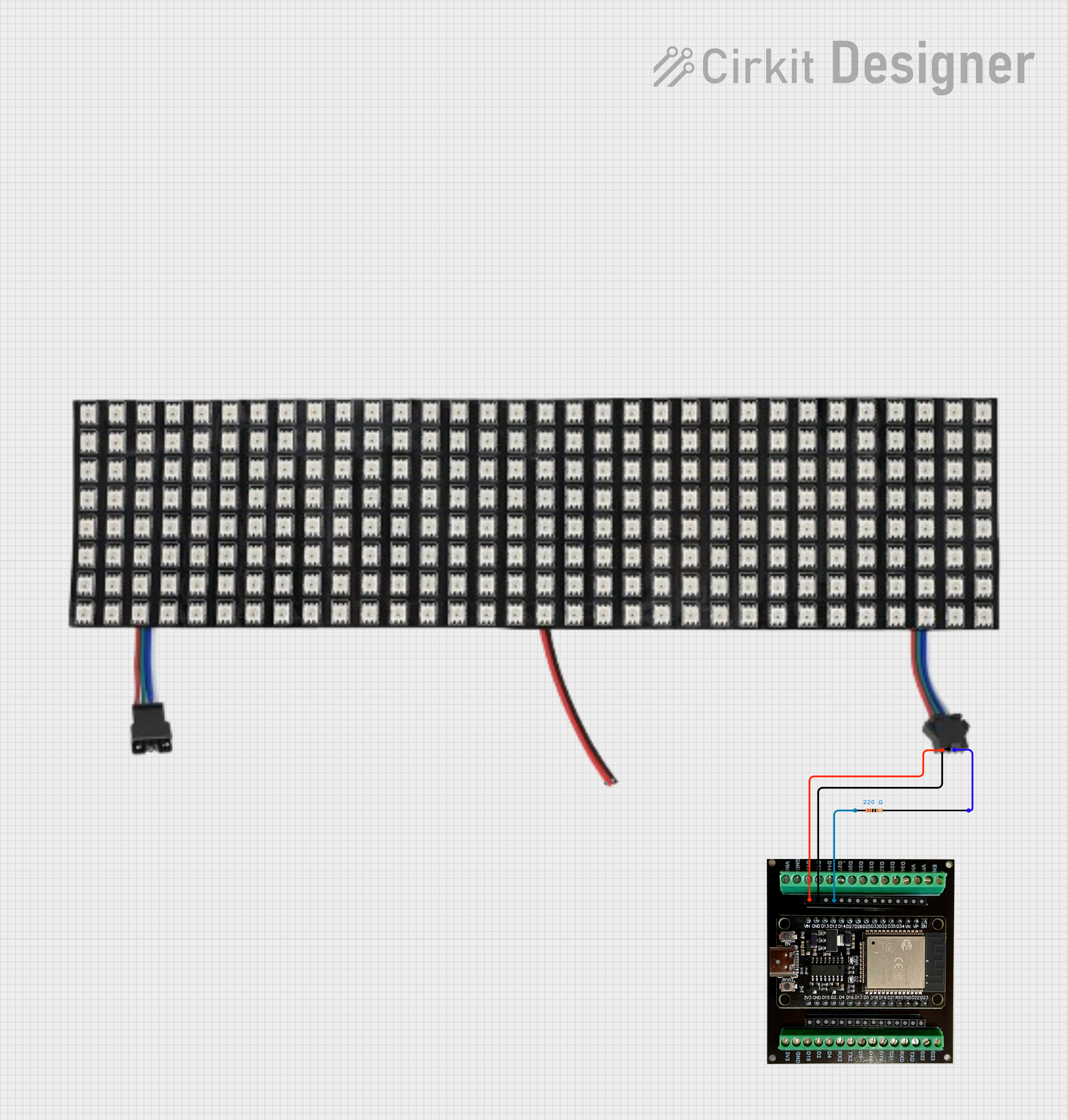
Explore Projects Built with LED matrix_small

 Open Project in Cirkit Designer
 Open Project in Cirkit Designer
 Open Project in Cirkit Designer
 Open Project in Cirkit Designer
Common Applications and Use Cases
- Digital clocks and timers
- Scrolling text displays
- Simple animations and patterns
- Status indicators in embedded systems
- Educational projects for learning about multiplexing and LED control
Technical Specifications
Below are the general technical specifications for a small LED matrix. Specific values may vary depending on the manufacturer and model.
| Parameter | Value |
|---|---|
| Operating Voltage | 3.3V to 5V |
| Operating Current | Typically 20mA per LED |
| LED Color | Red, Green, Blue, or Multicolor |
| Matrix Configuration | Commonly 8x8, 5x7, or 16x16 |
| Control Method | Multiplexing or Driver IC (e.g., MAX7219) |
| Dimensions | Varies (e.g., 32mm x 32mm for 8x8) |
| Interface | Direct GPIO or Serial (SPI/I2C) |
Pin Configuration and Descriptions
The pin configuration of an LED matrix depends on whether it is a raw matrix or one with an integrated driver IC. Below is an example of an 8x8 LED matrix with a MAX7219 driver IC:
| Pin | Name | Description |
|---|---|---|
| 1 | VCC | Power supply (3.3V or 5V) |
| 2 | GND | Ground |
| 3 | DIN | Serial data input |
| 4 | CS | Chip select (active low) |
| 5 | CLK | Serial clock input |
| 6 | NC | Not connected (varies by model) |
For raw LED matrices without a driver IC, pins are typically arranged as rows and columns, with each pin corresponding to a specific row or column in the grid.
Usage Instructions
How to Use the Component in a Circuit
- Power Supply: Connect the VCC and GND pins to a 3.3V or 5V power source, depending on the matrix's specifications.
- Control Interface: If using a driver IC (e.g., MAX7219), connect the DIN, CS, and CLK pins to the microcontroller's GPIO pins. For raw matrices, use multiplexing techniques to control individual LEDs.
- Resistors: For raw matrices, use current-limiting resistors to prevent overdriving the LEDs.
- Microcontroller: Use a microcontroller (e.g., Arduino UNO) to send control signals to the matrix.
Important Considerations and Best Practices
- Current Limiting: Always use appropriate resistors or rely on the driver IC's built-in current limiting to protect the LEDs.
- Refresh Rate: Ensure a high enough refresh rate (e.g., >60Hz) to avoid flickering.
- Power Supply: Verify that your power supply can handle the total current draw of the matrix.
- Driver IC: Use a driver IC like the MAX7219 for simplified control and reduced GPIO usage.
Example Code for Arduino UNO
Below is an example of how to control an 8x8 LED matrix with a MAX7219 driver IC using the Arduino UNO and the LedControl library.
#include <LedControl.h>

// Initialize the LedControl library
// Parameters: DIN pin, CLK pin, CS pin, number of devices
LedControl lc = LedControl(12, 11, 10, 1);

void setup() {
  // Wake up the MAX7219 from power-saving mode
  lc.shutdown(0, false);
  // Set brightness (0 = dim, 15 = bright)
  lc.setIntensity(0, 8);
  // Clear the display
  lc.clearDisplay(0);
}

void loop() {
  // Display a simple pattern (diagonal line)
  for (int i = 0; i < 8; i++) {
    lc.setLed(0, i, i, true); // Turn on LED at row i, column i
    delay(200);              // Wait 200ms
  }
  delay(1000);               // Pause for 1 second
  lc.clearDisplay(0);        // Clear the display
}
Troubleshooting and FAQs
Common Issues and Solutions
No LEDs Lighting Up
- Solution: Check the power connections (VCC and GND). Ensure the microcontroller is properly connected to the control pins (DIN, CS, CLK).
- Tip: Use a multimeter to verify voltage levels.
Flickering LEDs
- Solution: Increase the refresh rate in your code or ensure the power supply is stable.
- Tip: Use a capacitor across the power supply to reduce noise.
Dim LEDs
- Solution: Check the brightness setting in your code or verify the current-limiting resistors.
- Tip: Ensure the power supply can provide sufficient current.
Incorrect Pattern Displayed
- Solution: Verify the wiring and ensure the correct pins are defined in your code.
- Tip: Double-check the matrix orientation and pinout.
FAQs
Q: Can I use multiple LED matrices in one project?
- A: Yes, you can daisy-chain multiple matrices if using a driver IC like the MAX7219. Update your code to handle multiple devices.
Q: Do I need a library to control the matrix?
- A: While you can write custom code, using a library like
LedControlsimplifies the process significantly.
- A: While you can write custom code, using a library like
Q: Can I use a 3.3V microcontroller with a 5V matrix?
- A: Yes, but you may need level shifters for the control signals to ensure proper operation.
By following this documentation, you can effectively integrate a small LED matrix into your projects and troubleshoot common issues.