Cirkit Designer Logo
Cirkit Designer
Your all-in-one circuit design IDE
Home / 
Component Documentation

How to Use Digital Multimeter: Examples, Pinouts, and Specs

Image of Digital Multimeter
Cirkit Designer LogoDesign with Digital Multimeter in Cirkit Designer

Introduction

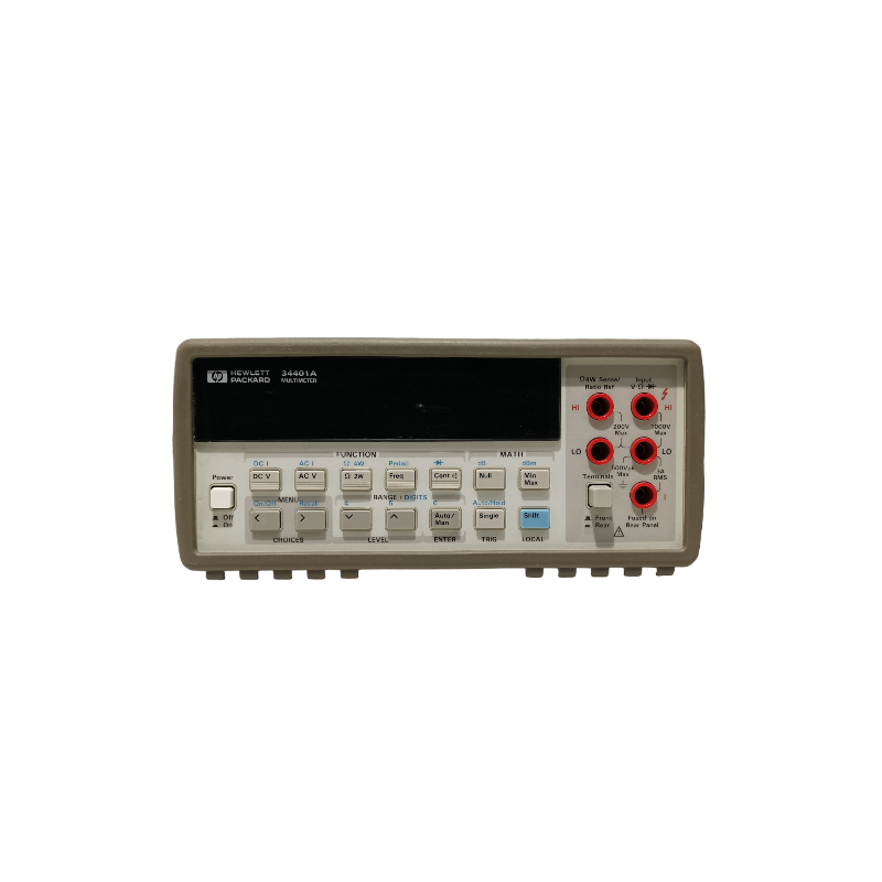
The Hewlett Packard 34401A Digital Multimeter is a versatile and precise measuring instrument capable of reading voltage, current, resistance, and other electrical properties. It is an essential tool for engineers, technicians, and hobbyists for troubleshooting and testing electronic circuits and systems. Common applications include electrical repair, laboratory work, and educational purposes.

Explore Projects Built with Digital Multimeter

Use Cirkit Designer to design, explore, and prototype these projects online. Some projects support real-time simulation. Click "Open Project" to start designing instantly!
Resistor Measurement Setup with Digital Multimeter and DC Power Supply
Image of 4_2A_circuit_diagram: A project utilizing Digital Multimeter in a practical application
This circuit consists of two 1k Ohm resistors connected in series between the 6V outputs of a DC power supply. A digital multimeter is connected across one of the resistors to measure the voltage drop, demonstrating a basic voltage measurement setup.
Cirkit Designer LogoOpen Project in Cirkit Designer
Resistor-Diode Circuit with Multimeter Current Measurement
Image of diode: A project utilizing Digital Multimeter in a practical application
This circuit consists of a power supply connected in series with a resistor and a diode. A multimeter is connected across the resistor to measure the current flowing through the resistor. The diode ensures current flows in one direction, protecting the circuit from potential reverse current damage.
Cirkit Designer LogoOpen Project in Cirkit Designer
DC Voltage Measurement Circuit with LM393 and Digital Volt/Ammeter
Image of Simple: A project utilizing Digital Multimeter in a practical application
This circuit consists of a DC power source connected to a mini digital volt/ammeter. The volt/ammeter measures the voltage supplied by the DC power source, with the ground and positive terminals of the power source connected to the corresponding ground and voltage reading pins of the volt/ammeter.
Cirkit Designer LogoOpen Project in Cirkit Designer
Arduino UNO Power Meter with I2C LCD Display and Current/Voltage Sensors
Image of Arduino UNO Simulator: A project utilizing Digital Multimeter in a practical application
This circuit is a power measurement system using an Arduino UNO, which reads voltage and current values from a voltage sensor and a current sensor, respectively. The measured values are displayed on a 16x2 I2C LCD and also sent to the serial monitor for debugging. Additionally, an LED is included for visual indication, and a 9V battery powers the entire setup.
Cirkit Designer LogoOpen Project in Cirkit Designer

Explore Projects Built with Digital Multimeter

Use Cirkit Designer to design, explore, and prototype these projects online. Some projects support real-time simulation. Click "Open Project" to start designing instantly!
Image of 4_2A_circuit_diagram: A project utilizing Digital Multimeter in a practical application
Resistor Measurement Setup with Digital Multimeter and DC Power Supply
This circuit consists of two 1k Ohm resistors connected in series between the 6V outputs of a DC power supply. A digital multimeter is connected across one of the resistors to measure the voltage drop, demonstrating a basic voltage measurement setup.
Cirkit Designer LogoOpen Project in Cirkit Designer
Image of diode: A project utilizing Digital Multimeter in a practical application
Resistor-Diode Circuit with Multimeter Current Measurement
This circuit consists of a power supply connected in series with a resistor and a diode. A multimeter is connected across the resistor to measure the current flowing through the resistor. The diode ensures current flows in one direction, protecting the circuit from potential reverse current damage.
Cirkit Designer LogoOpen Project in Cirkit Designer
Image of Simple: A project utilizing Digital Multimeter in a practical application
DC Voltage Measurement Circuit with LM393 and Digital Volt/Ammeter
This circuit consists of a DC power source connected to a mini digital volt/ammeter. The volt/ammeter measures the voltage supplied by the DC power source, with the ground and positive terminals of the power source connected to the corresponding ground and voltage reading pins of the volt/ammeter.
Cirkit Designer LogoOpen Project in Cirkit Designer
Image of Arduino UNO Simulator: A project utilizing Digital Multimeter in a practical application
Arduino UNO Power Meter with I2C LCD Display and Current/Voltage Sensors
This circuit is a power measurement system using an Arduino UNO, which reads voltage and current values from a voltage sensor and a current sensor, respectively. The measured values are displayed on a 16x2 I2C LCD and also sent to the serial monitor for debugging. Additionally, an LED is included for visual indication, and a 9V battery powers the entire setup.
Cirkit Designer LogoOpen Project in Cirkit Designer

Technical Specifications

General Features

  • Display: 6½ digit resolution
  • Measurement Speed: Up to 1000 readings/second
  • Interface: GPIB, RS-232

Measurement Capabilities

  • DC Voltage: 100 mV to 1000 V
  • AC Voltage: 100 mV to 750 V
  • DC Current: 10 mA to 3 A
  • AC Current: 10 mA to 3 A
  • Resistance: 100 ohms to 100 megaohms
  • Continuity and Diode Test: Yes

Pin Configuration and Descriptions

Pin Number Description
COM Common ground
V/Ω Voltage/Resistance
I Current
LO Low side measurement

Usage Instructions

Initial Setup

  1. Connect the multimeter to a power source.
  2. Turn on the multimeter using the power button.
  3. Select the desired measurement function (e.g., voltage, current, resistance).
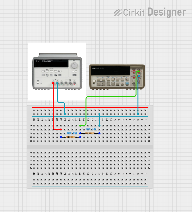
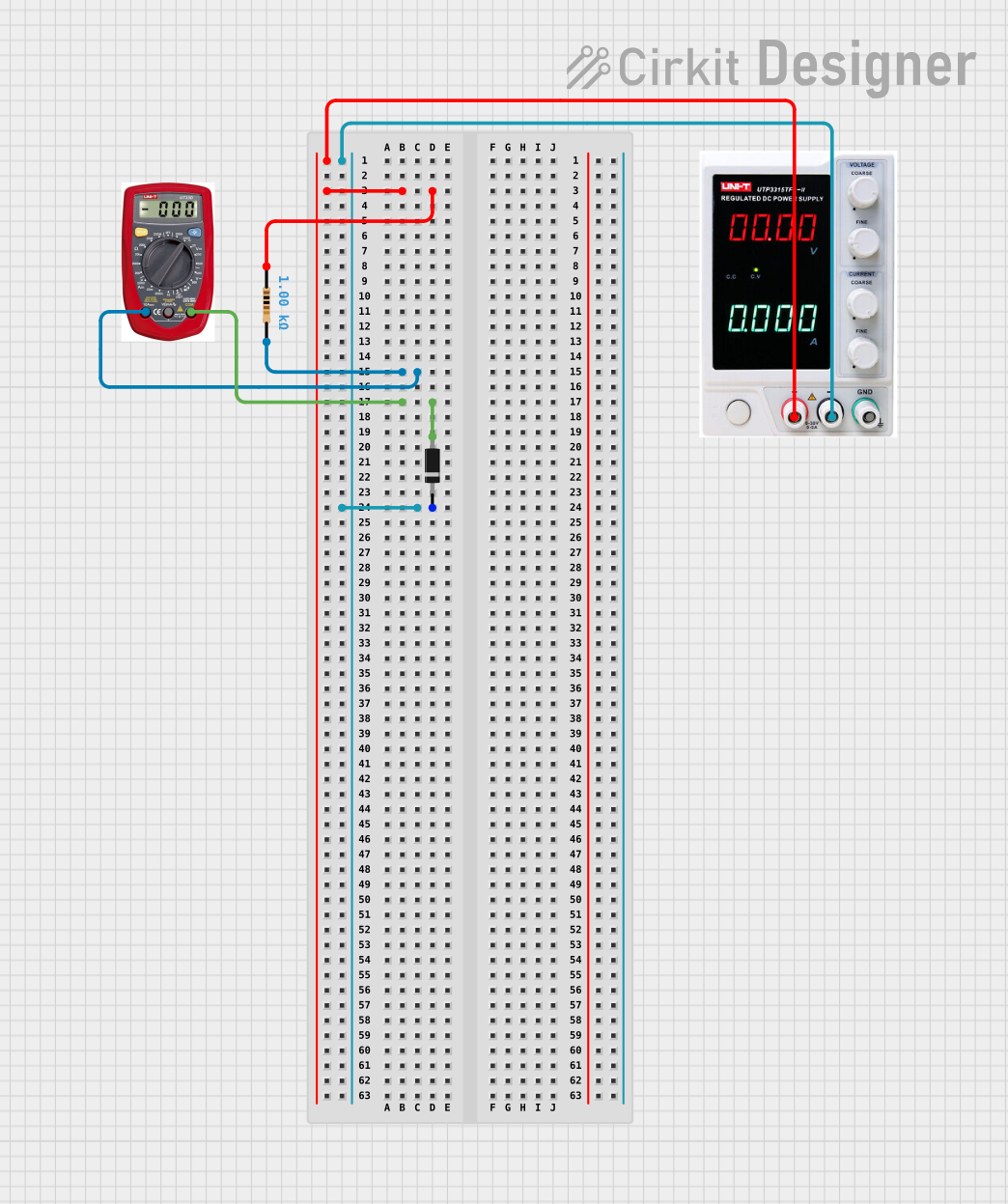
Measuring Voltage

  1. Connect the black lead to the COM jack.
  2. Connect the red lead to the V/Ω jack.
  3. Connect the leads across the component or circuit you wish to measure.
  4. Read the voltage measurement on the display.

Measuring Current

  1. Connect the black lead to the COM jack.
  2. Connect the red lead to the I jack.
  3. Break the circuit where you want to measure current and connect the multimeter in series.
  4. Read the current measurement on the display.

Measuring Resistance

  1. Ensure the circuit is de-energized and capacitors are discharged.
  2. Connect the black lead to the COM jack.
  3. Connect the red lead to the V/Ω jack.
  4. Connect the leads across the resistor or component.
  5. Read the resistance on the display.

Best Practices

  • Always start with the highest measurement range to prevent damage to the multimeter.
  • Ensure the multimeter is set to the correct measurement type before connecting it to a circuit.
  • Do not measure resistance in a live circuit.
  • Use the proper terminals for current measurements to avoid damaging the multimeter.

Troubleshooting and FAQs

Common Issues

  • Incorrect Readings: Ensure the multimeter is correctly configured for the type of measurement and that the leads are properly connected.
  • No Power: Check the power source and the multimeter's fuse.
  • Unstable Readings: Ensure there are no loose connections and that the component being measured is not faulty.

FAQs

  • Q: Can the HP 34401A measure capacitance?
    • A: No, the HP 34401A does not have a capacitance measurement function.
  • Q: What safety precautions should I take when using the multimeter?
    • A: Always use the correct measurement setting, observe proper polarity, and never exceed the maximum input ratings.

For more detailed troubleshooting, refer to the HP 34401A user manual or contact technical support.


Please note that the HP 34401A Digital Multimeter is not typically connected to an Arduino UNO or similar microcontroller platforms. It is a standalone measurement tool with its own display and user interface. Therefore, no Arduino-related code is applicable for this device.