How to Use WEMOS ESP32 D1 R32: Examples, Pinouts, and Specs
Introduction
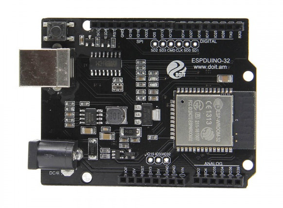
The WEMOS ESP32 D1 R32 is a versatile microcontroller board based on the powerful ESP32 chip. It combines robust processing capabilities with built-in Wi-Fi and Bluetooth connectivity, making it an excellent choice for Internet of Things (IoT) projects, wireless communication, and rapid prototyping. Its Arduino UNO form factor ensures compatibility with a wide range of shields and accessories, making it user-friendly for both beginners and experienced developers.
Explore Projects Built with WEMOS ESP32 D1 R32


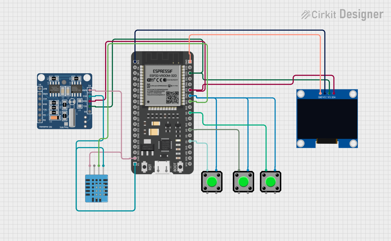

Explore Projects Built with WEMOS ESP32 D1 R32
Common Applications and Use Cases
- IoT devices and smart home automation
- Wireless sensor networks
- Remote data logging and monitoring
- Robotics and automation
- Prototyping and educational projects
Technical Specifications
The WEMOS ESP32 D1 R32 offers a range of features and specifications that make it a powerful and flexible development board.
Key Technical Details
- Microcontroller: ESP32 dual-core processor
- Clock Speed: Up to 240 MHz
- Flash Memory: 4 MB
- SRAM: 520 KB
- Connectivity: Wi-Fi 802.11 b/g/n, Bluetooth 4.2 (Classic and BLE)
- Operating Voltage: 3.3V
- Input Voltage (VIN): 7-12V
- Digital I/O Pins: 17
- Analog Input Pins (ADC): 6
- PWM Pins: 16
- UART Interfaces: 2
- SPI Interfaces: 2
- I2C Interfaces: 1
- USB Interface: Micro-USB for programming and power
- Dimensions: Compatible with Arduino UNO form factor
Pin Configuration and Descriptions
The WEMOS ESP32 D1 R32 pinout is designed to be compatible with Arduino shields while providing access to the ESP32's advanced features.
| Pin | Label | Description |
|---|---|---|
| 1 | VIN | Input voltage (7-12V) for powering the board. |
| 2 | 3V3 | 3.3V output for powering external components. |
| 3 | GND | Ground pin. |
| 4 | D0-D13 | Digital I/O pins (can be used for GPIO, PWM, etc.). |
| 5 | A0-A5 | Analog input pins (ADC). |
| 6 | TX, RX | UART communication pins. |
| 7 | SCL, SDA | I2C communication pins. |
| 8 | SPI (MISO, MOSI, SCK, SS) | SPI communication pins. |
| 9 | EN | Enable pin to reset the board. |
| 10 | RST | Reset pin to restart the microcontroller. |
Usage Instructions
The WEMOS ESP32 D1 R32 is easy to use and program, especially with the Arduino IDE. Below are the steps to get started and some best practices for using the board.
How to Use the Component in a Circuit
- Powering the Board:
- Use the micro-USB port to power the board (5V) or connect an external power source to the VIN pin (7-12V).
- Programming the Board:
- Install the ESP32 board package in the Arduino IDE.
- Select the correct board (
WEMOS D1 R32) and port in the Arduino IDE. - Write your code and upload it via the micro-USB connection.
- Connecting Peripherals:
- Use the digital and analog pins to connect sensors, actuators, and other peripherals.
- Ensure that external components operate at 3.3V to avoid damaging the board.
Important Considerations and Best Practices
- Voltage Levels: The ESP32 operates at 3.3V. Avoid connecting 5V signals directly to the GPIO pins.
- Wi-Fi and Bluetooth: Ensure a stable power supply when using wireless features, as they can draw significant current.
- Pin Multiplexing: Some pins have multiple functions (e.g., GPIO, ADC, PWM). Check the ESP32 datasheet to avoid conflicts.
- Heat Management: The ESP32 can get warm during operation. Ensure proper ventilation if used in an enclosed space.
Example Code for Arduino IDE
Below is an example of how to connect the WEMOS ESP32 D1 R32 to a Wi-Fi network and blink an LED.
#include <WiFi.h> // Include the Wi-Fi library

const char* ssid = "Your_SSID";       // Replace with your Wi-Fi network name
const char* password = "Your_PASSWORD"; // Replace with your Wi-Fi password
const int ledPin = 2;                 // Built-in LED pin (GPIO2)

void setup() {
  pinMode(ledPin, OUTPUT);            // Set the LED pin as an output
  Serial.begin(115200);               // Start the serial communication
  Serial.println("Connecting to Wi-Fi...");

  WiFi.begin(ssid, password);         // Connect to the Wi-Fi network
  while (WiFi.status() != WL_CONNECTED) {
    delay(500);                       // Wait for the connection to establish
    Serial.print(".");
  }
  Serial.println("\nWi-Fi connected!");
  Serial.print("IP Address: ");
  Serial.println(WiFi.localIP());     // Print the device's IP address
}

void loop() {
  digitalWrite(ledPin, HIGH);         // Turn the LED on
  delay(1000);                        // Wait for 1 second
  digitalWrite(ledPin, LOW);          // Turn the LED off
  delay(1000);                        // Wait for 1 second
}
Troubleshooting and FAQs
Common Issues Users Might Face
- Board Not Detected in Arduino IDE:
- Ensure the correct USB driver is installed for the ESP32.
- Check that the correct board and port are selected in the Arduino IDE.
- Wi-Fi Connection Fails:
- Double-check the SSID and password.
- Ensure the Wi-Fi network is within range and operational.
- GPIO Pin Malfunction:
- Verify that the pin is not being used for multiple functions.
- Ensure the connected components are operating at 3.3V.
Solutions and Tips for Troubleshooting
- Serial Monitor Debugging: Use
Serial.print()statements to debug your code and monitor the board's behavior. - Power Supply Issues: If the board resets or behaves erratically, use a stable power source with sufficient current (at least 500mA).
- Firmware Update: Ensure the ESP32 firmware is up to date to avoid compatibility issues.
By following this documentation, you can effectively utilize the WEMOS ESP32 D1 R32 for a wide range of projects and applications.