How to Use Pilot Lamp Green: Examples, Pinouts, and Specs

Introduction
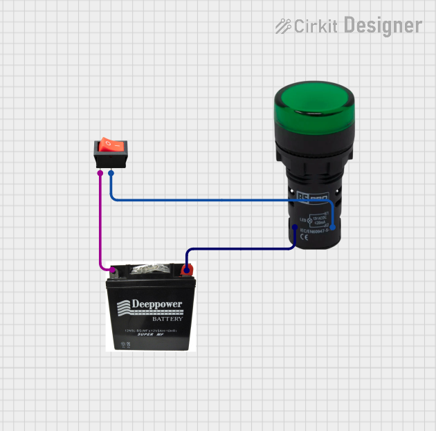
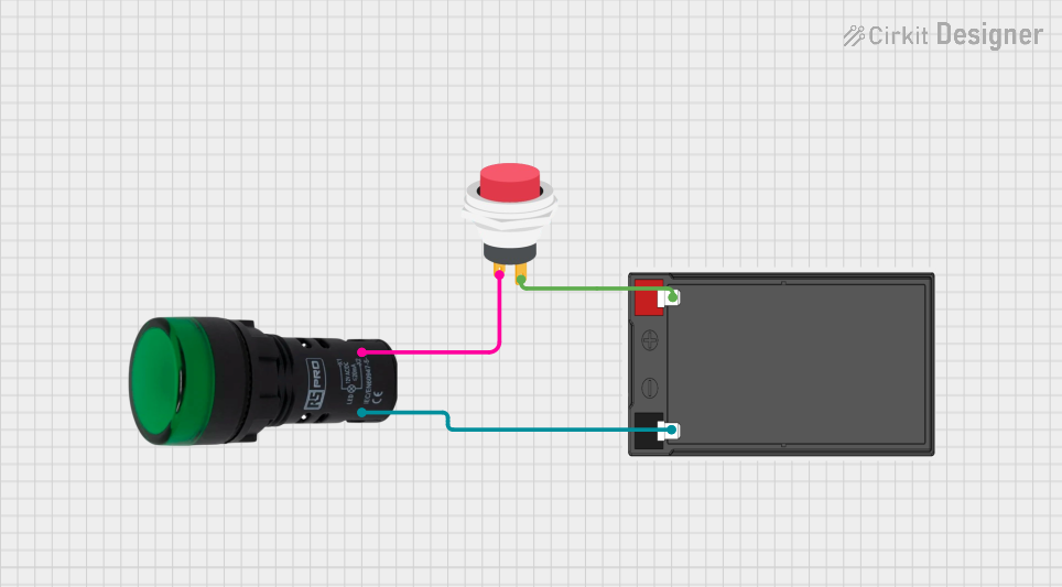
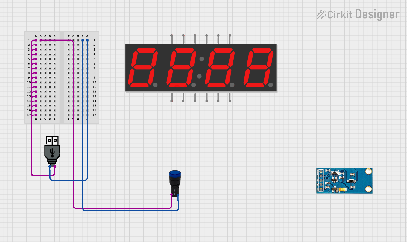
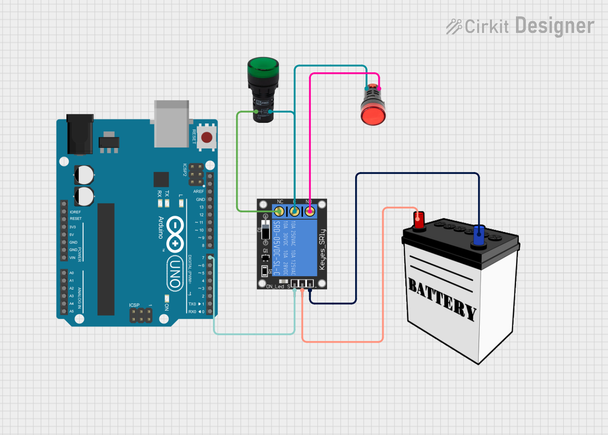
A Pilot Lamp Green is a small, yet significant electronic component that serves as an indicator light. When powered on, it emits a green light, which is commonly used to signal the operational status of a device or circuit. These lamps are widely used in control panels, dashboards, and various electronic appliances to provide a visual confirmation that the system is functioning correctly or to alert users to specific conditions.
Explore Projects Built with Pilot Lamp Green
Explore Projects Built with Pilot Lamp Green
Common Applications and Use Cases
- Control Panels: To indicate power on/off status.
- Machinery: To show that the machine is in a safe state for operation.
- Consumer Electronics: As a power or status indicator.
- Automotive: On dashboards to indicate various vehicle functions.
Technical Specifications
Key Technical Details
- Rated Voltage: 12V DC
- Operating Current: 10mA
- Power Consumption: 120mW
- Luminous Intensity: Typically 20 mcd (millicandela)
- Lifespan: Approximately 100,000 hours
- Operating Temperature: -20°C to 70°C
Pin Configuration and Descriptions
| Pin Number | Description |
|---|---|
| 1 | Anode (+) |
| 2 | Cathode (-) |
Usage Instructions
How to Use the Pilot Lamp Green in a Circuit
- Power Source: Ensure that the power source provides a DC voltage that matches the rated voltage of the Pilot Lamp Green (12V DC).
- Current Limiting: Incorporate a current-limiting resistor in series with the lamp to prevent excessive current flow that could damage the lamp.
- Wiring: Connect the anode (positive) pin of the lamp to the positive terminal of the power source through the current-limiting resistor. Connect the cathode (negative) pin directly to the negative terminal of the power source.
- Testing: Once connected, apply power to the circuit and observe the lamp. It should emit a green light if properly connected and powered.
Important Considerations and Best Practices
- Polarity: Be mindful of the polarity when connecting the Pilot Lamp Green. Reversing the polarity may prevent the lamp from lighting up.
- Resistor Selection: To calculate the value of the current-limiting resistor, use Ohm's law:
R = (Vsource - Vlamp) / Ilamp, whereVsourceis the source voltage,Vlampis the lamp's rated voltage, andIlampis the lamp's operating current. - Heat Dissipation: Ensure that the current-limiting resistor can handle the power dissipation without overheating.
Troubleshooting and FAQs
Common Issues
- Lamp Does Not Illuminate: Check the connections for proper polarity and ensure that the power source is functioning.
- Dim Light: Verify that the voltage level is correct and that the current-limiting resistor is of the appropriate value.
- Lamp Burns Out Quickly: Ensure that the current through the lamp does not exceed the rated operating current.
Solutions and Tips for Troubleshooting
- Double-Check Wiring: Revisit the circuit connections and make sure they are secure and correctly oriented.
- Measure Voltage and Current: Use a multimeter to measure the voltage across the lamp and the current flowing through it to ensure they match the specifications.
- Resistor Replacement: If the resistor is not the correct value or is damaged, replace it with a suitable one.
FAQs
Q: Can I use the Pilot Lamp Green with an AC power source? A: No, this lamp is rated for DC voltage. Using it with an AC source may damage the lamp.
Q: What happens if I connect the lamp without a current-limiting resistor? A: Connecting the lamp directly to a power source without a current-limiting resistor may cause it to draw excessive current, leading to premature failure.
Q: Is the Pilot Lamp Green suitable for outdoor use? A: The suitability for outdoor use depends on the environmental conditions and whether the lamp has appropriate protection. Check the operating temperature range and ensure it is housed in a weatherproof enclosure if necessary.
Example Code for Arduino UNO
// Define the pin where the Pilot Lamp Green is connected
const int pilotLampPin = 13; // Using the built-in LED pin for demonstration

void setup() {
  // Set the pilot lamp pin as an output
  pinMode(pilotLampPin, OUTPUT);
}

void loop() {
  // Turn on the Pilot Lamp Green
  digitalWrite(pilotLampPin, HIGH);
  delay(1000); // Keep the lamp on for 1 second

  // Turn off the Pilot Lamp Green
  digitalWrite(pilotLampPin, LOW);
  delay(1000); // Keep the lamp off for 1 second
}
Note: In this example, we're using the built-in LED on the Arduino UNO as a stand-in for the Pilot Lamp Green. When connecting an actual Pilot Lamp Green, ensure it is connected through a current-limiting resistor and that the voltage levels are appropriate for the lamp.