
How to Use ESP32 UWD: Examples, Pinouts, and Specs
 Design with ESP32 UWD in Cirkit Designer
Introduction
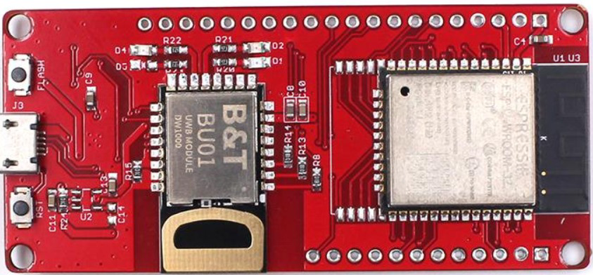
The ESP32 UWD, manufactured by MakerFabs (Part ID: DW1000), is a powerful and versatile microcontroller designed for Internet of Things (IoT) applications. It combines integrated Wi-Fi and Bluetooth capabilities with a robust set of features, including multiple GPIO pins, ADCs, and support for various communication protocols. This makes it an excellent choice for smart devices, home automation, industrial control systems, and other connected projects.
Explore Projects Built with ESP32 UWD
 Open Project in Cirkit Designer
 Open Project in Cirkit Designer
 Open Project in Cirkit Designer
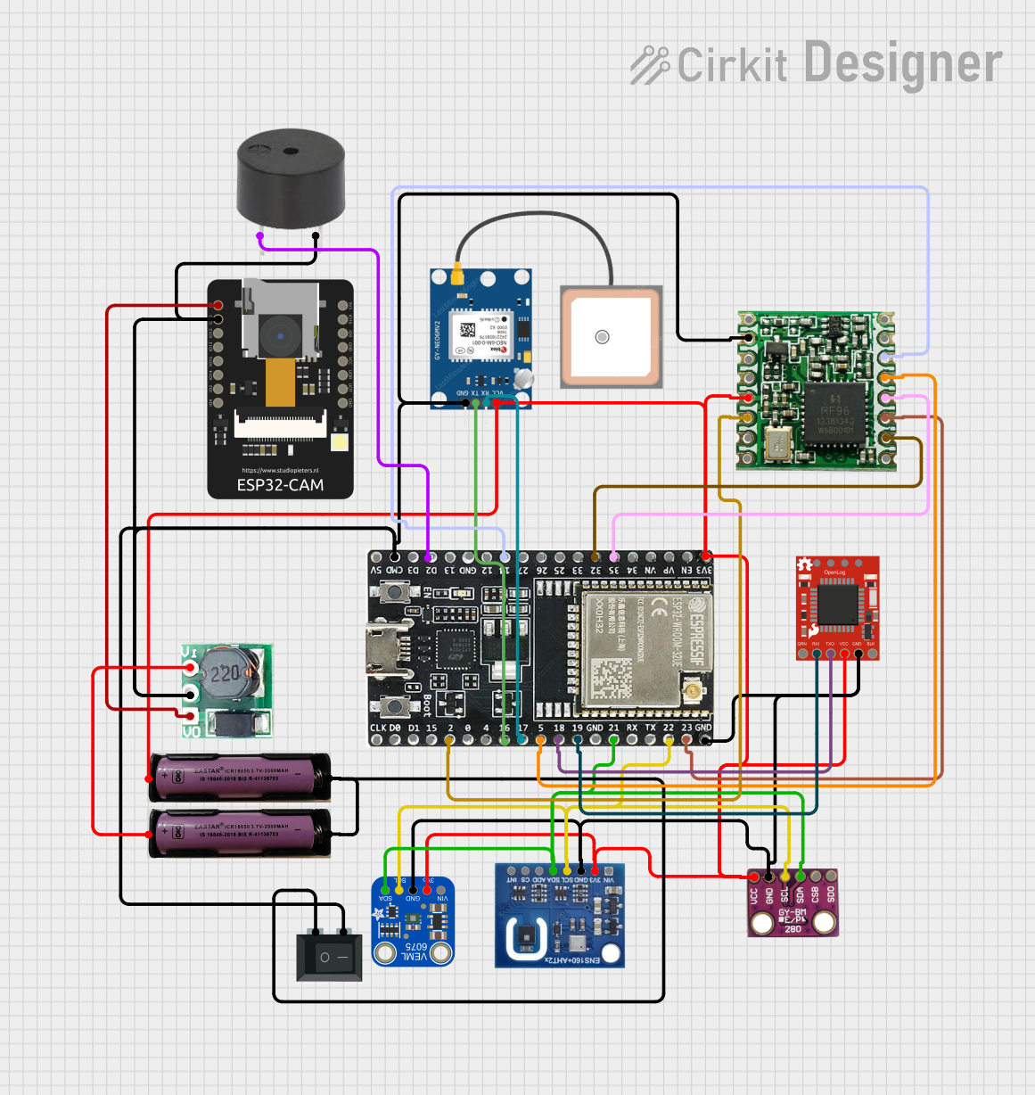 Open Project in Cirkit Designer
Explore Projects Built with ESP32 UWD
Open Project in Cirkit DesignerOpen Project in Cirkit DesignerOpen Project in Cirkit DesignerOpen Project in Cirkit DesignerCommon Applications
- Smart home devices (e.g., smart lights, thermostats)
- Industrial automation and monitoring
- Wearable technology
- Wireless sensor networks
- Robotics and drones
- IoT prototyping and development
Technical Specifications
Key Technical Details
| Parameter | Specification |
|---|---|
| Microcontroller | ESP32 Dual-Core Processor |
| Clock Speed | Up to 240 MHz |
| Flash Memory | 4 MB (expandable) |
| SRAM | 520 KB |
| Wi-Fi | 802.11 b/g/n |
| Bluetooth | Bluetooth 4.2 (Classic + BLE) |
| GPIO Pins | 34 |
| ADC Channels | 18 (12-bit resolution) |
| Communication Protocols | UART, SPI, I2C, I2S, CAN, PWM |
| Operating Voltage | 3.3V |
| Input Voltage Range | 3.0V - 3.6V |
| Power Consumption | Ultra-low power (varies by mode) |
| Dimensions | 25.5 mm x 18 mm |
| Operating Temperature | -40°C to +85°C |
Pin Configuration and Descriptions
The ESP32 UWD features a total of 38 pins, with 34 GPIO pins that can be configured for various functions. Below is a summary of the pin configuration:
| Pin Number | Pin Name | Functionality |
|---|---|---|
| 1 | EN | Enable pin (active high) |
| 2 | IO0 | GPIO0, boot mode selection |
| 3 | IO1 | GPIO1, UART TX |
| 4 | IO2 | GPIO2, ADC2 channel |
| 5 | IO3 | GPIO3, UART RX |
| 6 | IO4 | GPIO4, PWM, ADC2 channel |
| 7 | IO5 | GPIO5, SPI CS |
| 8 | IO12 | GPIO12, ADC2 channel, touch sensor |
| 9 | IO13 | GPIO13, ADC2 channel, touch sensor |
| 10 | IO14 | GPIO14, PWM, ADC2 channel |
| ... | ... | ... (Refer to the full datasheet) |
| 37 | GND | Ground |
| 38 | 3V3 | 3.3V power supply |
Note: Some GPIO pins have dual or specialized functions. Refer to the ESP32 UWD datasheet for detailed pin multiplexing information.
Usage Instructions
How to Use the ESP32 UWD in a Circuit
- Power Supply: Ensure the ESP32 UWD is powered with a stable 3.3V supply. Avoid exceeding the input voltage range (3.0V - 3.6V) to prevent damage.
- GPIO Configuration: Configure the GPIO pins as input, output, or alternate functions (e.g., ADC, PWM) based on your application.
- Programming: Use the Arduino IDE, PlatformIO, or ESP-IDF to program the ESP32 UWD. Install the necessary board support package (BSP) for ESP32.
- Communication: Utilize the built-in Wi-Fi and Bluetooth capabilities for wireless communication. Libraries such as
WiFi.handBluetoothSerial.hcan simplify development. - Peripherals: Connect sensors, actuators, or other peripherals to the GPIO pins. Use appropriate pull-up or pull-down resistors if required.
Important Considerations
- Voltage Levels: The ESP32 UWD operates at 3.3V logic levels. Use level shifters if interfacing with 5V devices.
- Power Modes: Leverage the ultra-low-power modes (e.g., deep sleep) for battery-powered applications.
- Antenna Placement: Ensure proper placement of the onboard antenna for optimal Wi-Fi and Bluetooth performance. Avoid placing metal objects near the antenna.
Example Code for Arduino UNO Integration
Below is an example of using the ESP32 UWD to connect to a Wi-Fi network and send data to a server:
#include <WiFi.h> // Include the Wi-Fi library

// Replace with your network credentials
const char* ssid = "Your_SSID";
const char* password = "Your_PASSWORD";

void setup() {
  Serial.begin(115200); // Initialize serial communication
  delay(1000);

  // Connect to Wi-Fi
  Serial.print("Connecting to Wi-Fi");
  WiFi.begin(ssid, password);
  while (WiFi.status() != WL_CONNECTED) {
    delay(500);
    Serial.print(".");
  }
  Serial.println("\nWi-Fi connected!");
  Serial.print("IP Address: ");
  Serial.println(WiFi.localIP()); // Print the device's IP address
}

void loop() {
  // Example: Send data to a server (replace with your server details)
  WiFiClient client;
  const char* server = "example.com";
  if (client.connect(server, 80)) {
    client.println("GET / HTTP/1.1");
    client.println("Host: example.com");
    client.println("Connection: close");
    client.println();
  }
  delay(10000); // Wait 10 seconds before sending the next request
}
Tip: Replace
Your_SSIDandYour_PASSWORDwith your Wi-Fi network credentials. Modify the server details as needed for your application.
Troubleshooting and FAQs
Common Issues
Wi-Fi Connection Fails
- Cause: Incorrect SSID or password.
- Solution: Double-check your network credentials and ensure the router is powered on.
ESP32 UWD Not Detected by Computer
- Cause: Missing USB driver or faulty USB cable.
- Solution: Install the correct USB-to-serial driver (e.g., CP210x or CH340) and try a different cable.
GPIO Pins Not Functioning as Expected
- Cause: Incorrect pin configuration or conflicting functions.
- Solution: Verify the pin mode in your code and check for pin conflicts in the datasheet.
High Power Consumption
- Cause: Device not in low-power mode.
- Solution: Use deep sleep mode when the device is idle to conserve power.
FAQs
Q: Can the ESP32 UWD operate on 5V?
A: No, the ESP32 UWD operates at 3.3V. Use a voltage regulator or level shifter for 5V systems.Q: How do I update the firmware?
A: Use the ESP32 Flash Download Tool or the Arduino IDE to upload new firmware.Q: Is the ESP32 UWD compatible with Arduino libraries?
A: Yes, the ESP32 UWD is fully compatible with most Arduino libraries, including Wi-Fi and Bluetooth libraries.Q: Can I use the ESP32 UWD for battery-powered projects?
A: Yes, the ESP32 UWD supports ultra-low-power modes, making it suitable for battery-powered applications.
For additional support, refer to the MakerFabs documentation or community forums.