How to Use Diode Image: Examples, Pinouts, and Specs
Introduction
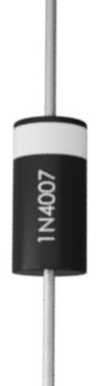
The IN4007 is a general-purpose rectifier diode designed to allow current to flow in one direction only, effectively acting as a one-way valve for electrical current. This semiconductor device is widely used in various electronic circuits for rectification, voltage blocking, and protection purposes. Its robust design and high voltage rating make it suitable for both low-power and high-power applications.
Explore Projects Built with Diode Image

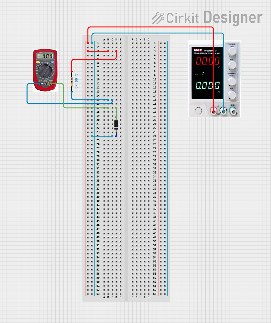
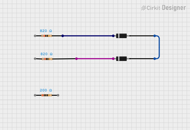
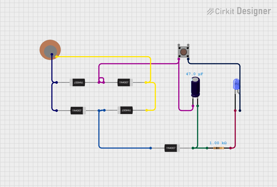
Explore Projects Built with Diode Image
Common Applications and Use Cases
- AC to DC rectification in power supplies
- Reverse polarity protection in circuits
- Voltage clamping and surge protection
- Freewheeling diodes in inductive loads (e.g., motors, relays)
- General-purpose signal rectification
Technical Specifications
The IN4007 diode is part of the 1N400x series, known for its reliability and versatility. Below are the key technical details:
| Parameter | Value |
|---|---|
| Manufacturer | IN4007 |
| Part ID | IN4007 |
| Maximum Repetitive Peak Reverse Voltage (VRRM) | 1000 V |
| Maximum RMS Voltage | 700 V |
| Maximum Average Forward Current (IF(AV)) | 1 A |
| Peak Forward Surge Current (IFSM) | 30 A (8.3 ms single half-sine wave) |
| Maximum Forward Voltage Drop (VF) | 1.1 V at 1 A |
| Reverse Current (IR) | 5 µA at 25°C, 50 µA at 1000 V |
| Operating Temperature Range | -55°C to +150°C |
| Package Type | DO-41 |
Pin Configuration and Descriptions
The IN4007 diode has two terminals:
| Pin | Name | Description |
|---|---|---|
| 1 | Anode | Positive terminal; current enters through this pin. |
| 2 | Cathode | Negative terminal; current exits through this pin. |
The cathode is typically marked with a silver or white band on the diode body.
Usage Instructions
How to Use the IN4007 in a Circuit
- Identify the Polarity: Locate the cathode (marked with a silver/white band) and the anode.
- Connect the Diode:
- For rectification, connect the anode to the positive side of the circuit and the cathode to the negative side.
- For reverse polarity protection, place the diode in series with the power supply, ensuring the anode is connected to the positive terminal.
- Verify Voltage and Current Ratings: Ensure the applied voltage and current do not exceed the diode's maximum ratings (e.g., 1000 V reverse voltage, 1 A forward current).
- Add a Resistor if Necessary: In some cases, a current-limiting resistor may be required to prevent excessive current through the diode.
Important Considerations and Best Practices
- Heat Dissipation: If the diode operates near its maximum current rating, consider adding a heatsink or ensuring proper ventilation to avoid overheating.
- Surge Protection: For circuits with high inrush currents, ensure the peak forward surge current (30 A) is not exceeded.
- Polarity Check: Always double-check the orientation of the diode before powering the circuit to avoid damage.
Example: Using the IN4007 with an Arduino UNO
The IN4007 can be used for reverse polarity protection in an Arduino UNO circuit. Below is an example:
Circuit Description
- The IN4007 is placed in series with the Arduino's power input to prevent damage if the power supply is connected in reverse.
Code Example
/* Example: Arduino UNO with IN4007 for reverse polarity protection
   This code demonstrates a simple LED blink program. The IN4007 diode
   protects the Arduino from reverse polarity damage. */

void setup() {
  pinMode(13, OUTPUT); // Set pin 13 as an output for the onboard LED
}

void loop() {
  digitalWrite(13, HIGH); // Turn the LED on
  delay(1000);            // Wait for 1 second
  digitalWrite(13, LOW);  // Turn the LED off
  delay(1000);            // Wait for 1 second
}
Troubleshooting and FAQs
Common Issues and Solutions
Diode Overheating:
- Cause: Excessive current or insufficient heat dissipation.
- Solution: Ensure the current through the diode does not exceed 1 A. Add a heatsink or improve ventilation if necessary.
No Current Flow Through the Diode:
- Cause: Incorrect polarity or damaged diode.
- Solution: Verify the orientation of the diode (anode to positive, cathode to negative). Test the diode with a multimeter to check for damage.
Voltage Drop Too High:
- Cause: Forward voltage drop of the diode (1.1 V at 1 A).
- Solution: If the voltage drop is critical, consider using a Schottky diode with a lower forward voltage drop.
FAQs
Q1: Can the IN4007 be used for high-frequency applications?
A1: No, the IN4007 is not suitable for high-frequency applications due to its relatively slow switching speed. Use a fast recovery or Schottky diode for such purposes.
Q2: What happens if the reverse voltage exceeds 1000 V?
A2: The diode will break down and may become permanently damaged. Always ensure the reverse voltage stays within the specified limit.
Q3: Can I use the IN4007 for AC to DC conversion?
A3: Yes, the IN4007 is commonly used in rectifier circuits for AC to DC conversion. Use it in a bridge rectifier configuration for full-wave rectification.
By following this documentation, you can effectively use the IN4007 diode in your electronic projects while avoiding common pitfalls.