How to Use AHD to Type-c USB capture Analog signal to digital USB camera module UVC Free: Examples, Pinouts, and Specs
Introduction
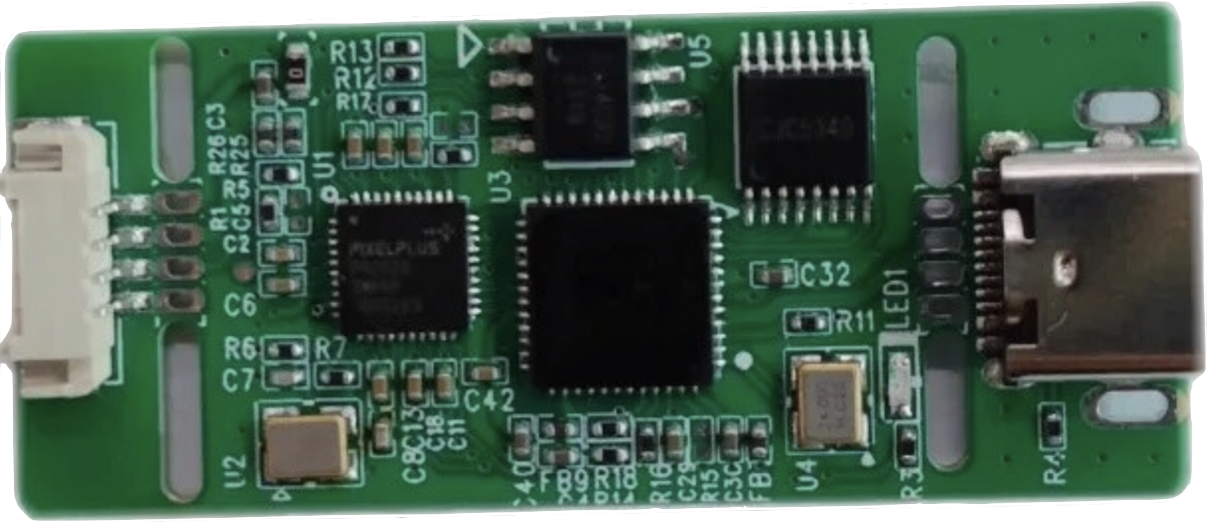
The AHD to Type-C USB Capture Analog Signal to Digital USB Camera Module is a versatile device designed to convert analog high-definition (AHD) video signals into digital USB video streams. This module supports UVC (USB Video Class) standards, meaning it does not require additional drivers for most modern operating systems. It is widely used in applications such as video surveillance, live streaming, video conferencing, and other scenarios where analog video sources need to be integrated into digital systems.
Common applications include:
- Converting AHD camera feeds to USB for use with computers or embedded systems.
- Integrating analog video sources into live streaming setups.
- Capturing video for video conferencing or remote monitoring.
- Testing and debugging AHD camera systems.
Explore Projects Built with AHD to Type-c USB capture Analog signal to digital USB camera module UVC Free


Explore Projects Built with AHD to Type-c USB capture Analog signal to digital USB camera module UVC Free
Technical Specifications
Key Technical Details
| Parameter | Specification |
|---|---|
| Input Signal Format | AHD (720p, 1080p supported) |
| Output Signal Format | USB Video Class (UVC) |
| Input Resolution | Up to 1920x1080 (1080p) |
| Output Resolution | Matches input resolution (up to 1080p) |
| Interface | Type-C USB |
| Power Supply | 5V (via USB Type-C port) |
| Operating System Support | Windows, macOS, Linux, Android (UVC compatible) |
| Dimensions | Compact module design (varies by manufacturer) |
| Operating Temperature | -10°C to 60°C |
Pin Configuration and Descriptions
The module typically has the following connectors:
Input Connector (AHD Signal)
| Pin Name | Description |
|---|---|
| Video In | AHD video signal input |
| GND | Ground connection for video input |
Output Connector (Type-C USB)
| Pin Name | Description |
|---|---|
| USB Data+ | USB positive data line |
| USB Data- | USB negative data line |
| VBUS | 5V power supply from USB |
| GND | Ground connection for USB |
Usage Instructions
How to Use the Component in a Circuit
Connect the AHD Video Source:
- Connect the AHD camera's video output to the module's
Video Inpin. - Ensure the
GNDpin of the AHD signal is properly connected to the module'sGND.
- Connect the AHD camera's video output to the module's
Connect the Module to a USB Host:
- Use a Type-C USB cable to connect the module to a USB host device (e.g., a computer, Raspberry Pi, or Android device).
- The module will be powered via the USB connection.
Verify UVC Compatibility:
- Ensure the host device supports UVC. Most modern operating systems (Windows, macOS, Linux, Android) natively support UVC devices.
Access the Video Stream:
- Open a video capture application (e.g., VLC Media Player, OBS Studio, or a custom application) on the host device.
- Select the module as the video input source.
Important Considerations and Best Practices
- Power Supply: Ensure the USB host device can provide sufficient power (5V) to the module. If using a USB hub, it should be powered.
- Cable Quality: Use high-quality cables for both the AHD input and USB output to minimize signal degradation.
- Resolution Matching: The module outputs video at the same resolution as the input. Ensure the AHD camera is configured to output a supported resolution (e.g., 720p or 1080p).
- Environmental Conditions: Operate the module within the specified temperature range (-10°C to 60°C) to avoid performance issues.
Example Code for Arduino UNO Integration
While the module is not directly compatible with Arduino UNO due to its USB-based interface, it can be used in conjunction with a USB host shield. Below is an example of how to initialize and detect the module using an Arduino UNO with a USB host shield:
#include <Usb.h>
#include <usbhub.h>
#include <usbh_uvc.h>

// Create USB and UVC objects
USB usb;
UVC uvc(&usb);

void setup() {
  Serial.begin(9600);
  if (usb.Init() == -1) {
    Serial.println("USB initialization failed. Check connections.");
    while (1); // Halt execution if USB initialization fails
  }
  Serial.println("USB initialized successfully.");
}

void loop() {
  usb.Task(); // Process USB tasks

  if (uvc.isReady()) {
    Serial.println("UVC device detected.");
    // Additional code to handle video stream can be added here
  } else {
    Serial.println("No UVC device detected.");
  }

  delay(1000); // Wait for 1 second before checking again
}
Note: The above code requires a USB host shield and the appropriate libraries (
Usb.h,usbhub.h,usbh_uvc.h). Ensure these are installed in your Arduino IDE.
Troubleshooting and FAQs
Common Issues Users Might Face
No Video Output Detected:
- Ensure the AHD camera is powered and outputting a supported resolution.
- Verify that the
Video InandGNDconnections are secure. - Check the USB connection to the host device.
Device Not Recognized by Host:
- Confirm that the host device supports UVC.
- Try using a different USB port or cable.
- Restart the host device and reconnect the module.
Poor Video Quality:
- Use high-quality cables for both AHD input and USB output.
- Ensure the AHD camera is configured to output a high-resolution signal.
Solutions and Tips for Troubleshooting
- Test with Multiple Applications: If the video stream is not visible, try using different video capture applications to rule out software issues.
- Update Host Drivers: Ensure the host device's USB and video drivers are up to date.
- Check Power Supply: If the module is not functioning, ensure the USB host provides sufficient power. Use a powered USB hub if necessary.
By following this documentation, users can effectively integrate and troubleshoot the AHD to Type-C USB Capture Analog Signal to Digital USB Camera Module in their projects.