How to Use 7-Segment Display: Examples, Pinouts, and Specs
Introduction
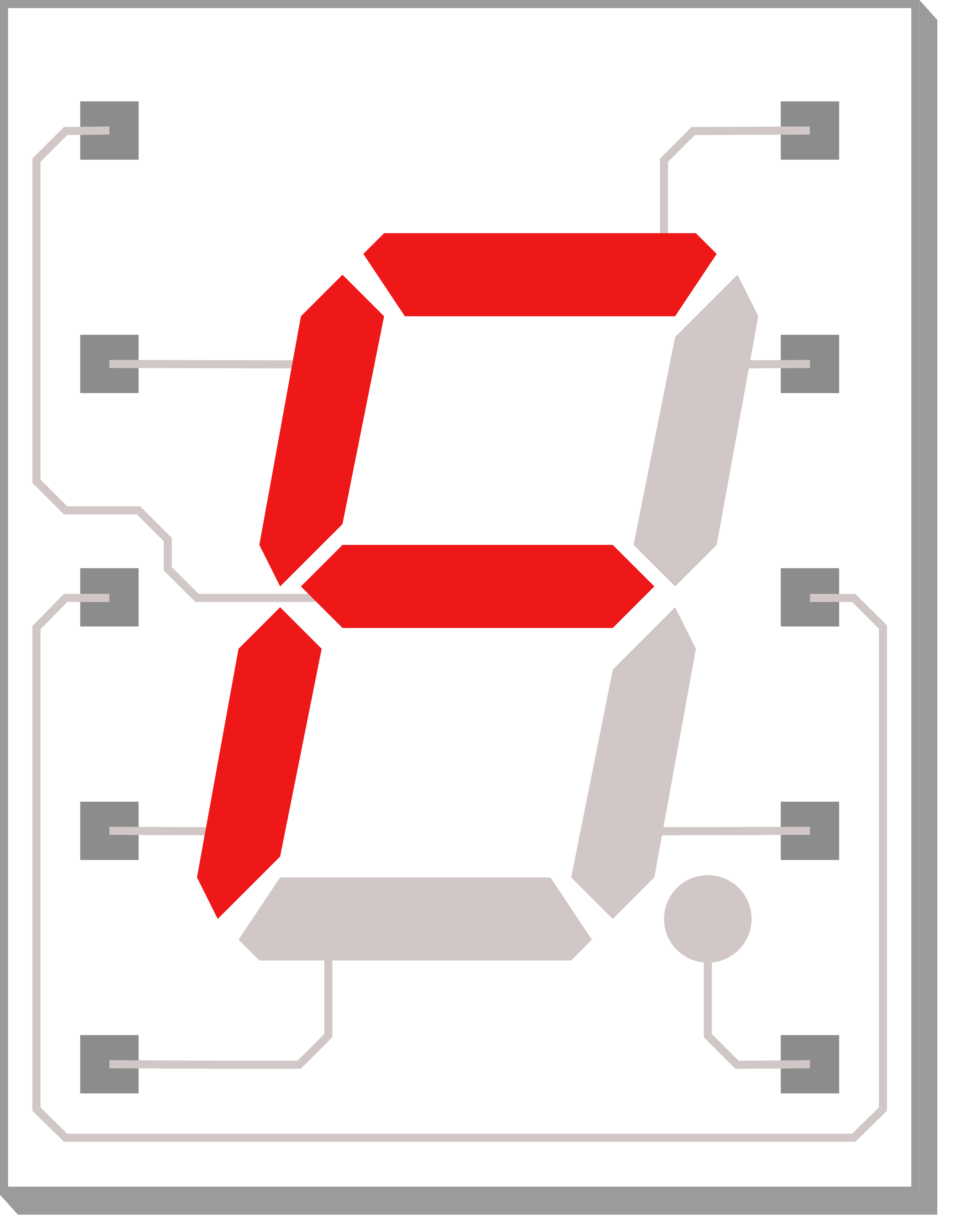
A 7-segment LED display is an electronic display device used to show numeric digits and a limited number of alphabetical characters. It consists of seven LEDs arranged in a rectangular fashion. Each LED is called a segment because when illuminated, the segment forms part of a numeral to be displayed. An additional eighth LED is sometimes used within the same package, this is normally for a decimal point (DP) or other indications.
Explore Projects Built with 7-Segment Display
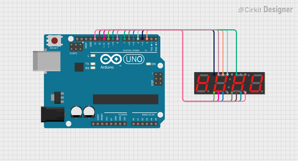
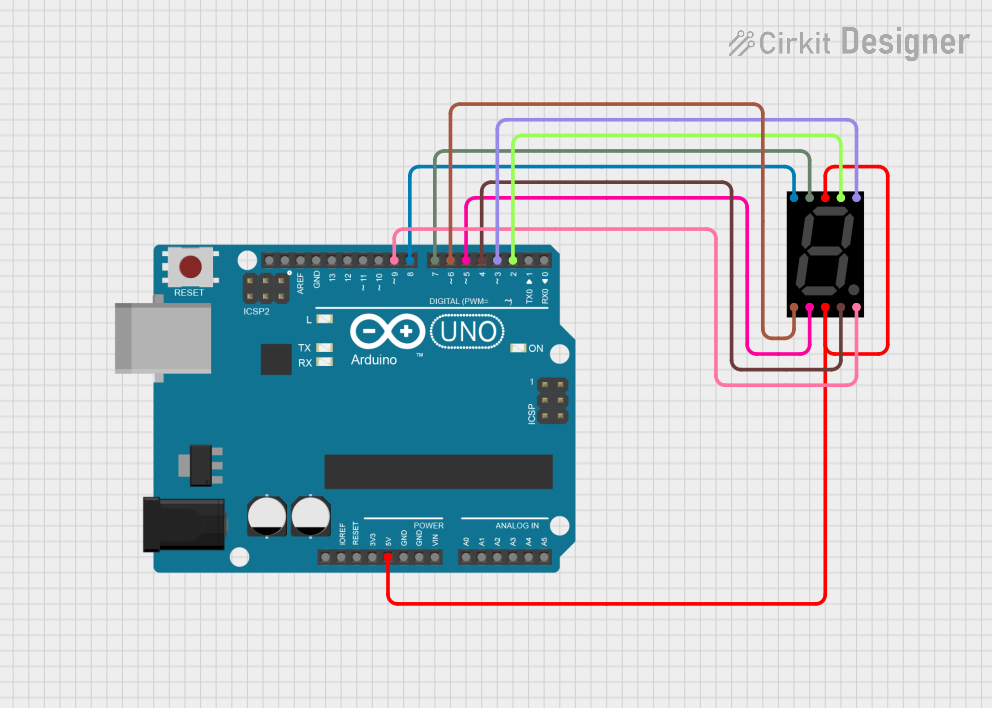
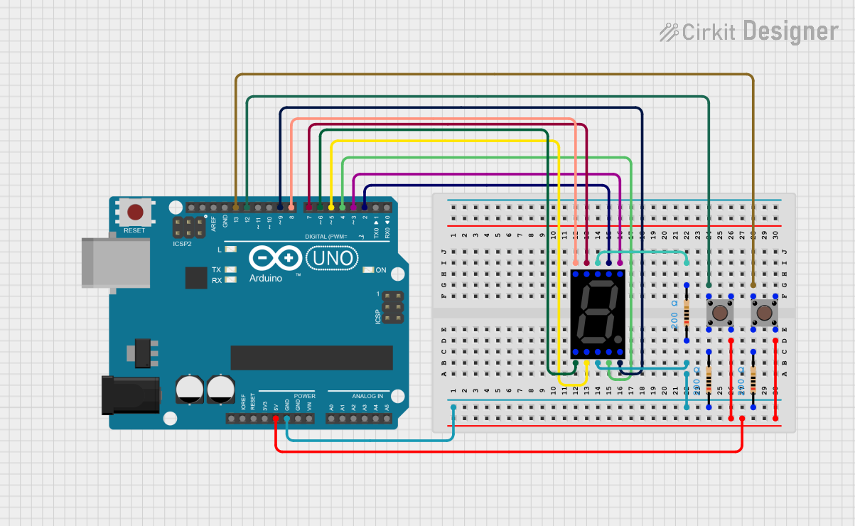
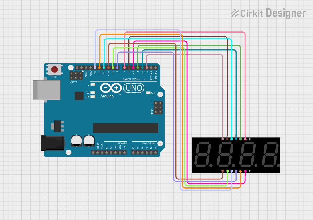
Explore Projects Built with 7-Segment Display
Common Applications and Use Cases
- Digital clocks and timers
- Electronic meters
- Basic calculators
- Price display in retail settings
- Scoreboards
Technical Specifications
Key Technical Details
- Forward Voltage (Typical): 2.0V - 2.2V per segment
- Forward Current: 10mA - 20mA per segment
- Luminous Intensity: Dependent on color and size, typically around 80-100 mcd
- Viewing Angle: ~120 degrees
Pin Configuration and Descriptions
| Pin Number | Segment | Description |
|---|---|---|
| 1 | E | Controls the bottom-left segment |
| 2 | D | Controls the bottom segment |
| 3 | DP | Controls the decimal point (if present) |
| 4 | C | Controls the bottom-right segment |
| 5 | G | Controls the middle segment |
| 6 | Common Anode/Cathode | Common pin for all segments (type depends on display) |
| 7 | F | Controls the top-left segment |
| 8 | A | Controls the top segment |
| 9 | B | Controls the top-right segment |
Note: The pinout can vary between manufacturers. Always consult the datasheet of the specific model you are using.
Usage Instructions
How to Use the Component in a Circuit
- Identify the Type: Determine if your 7-segment display is common anode or common cathode, as this will affect how you power the segments.
- Connect the Common Pin: For common anode displays, connect the common pin to VCC. For common cathode displays, connect it to GND.
- Resistors: Connect a current-limiting resistor in series with each segment to prevent damage to the LEDs. The value of the resistor can be calculated using Ohm's law:
R = (V_supply - V_forward) / I_forward. - Control Pins: Connect the other pins to the microcontroller or other control circuitry to turn on or off each segment.
Important Considerations and Best Practices
- Avoid powering all segments at maximum current simultaneously to prevent excessive power consumption and heat.
- Use multiplexing if you need to control multiple displays to save on control pins.
- Ensure that the power supply can handle the cumulative current draw when all segments are lit.
Example Code for Arduino UNO
// Define the LED segment and digital pins on the Arduino
int segments[] = {2, 3, 4, 5, 6, 7, 8, 9}; // A, B, C, D, E, F, G, DP

void setup() {
  // Set all the pins to output mode
  for (int i = 0; i < 8; i++) {
    pinMode(segments[i], OUTPUT);
  }
}

void loop() {
  // Display the digit '8'
  for (int i = 0; i < 8; i++) {
    digitalWrite(segments[i], HIGH);
  }
  delay(1000); // Wait for 1 second

  // Turn off all segments
  for (int i = 0; i < 8; i++) {
    digitalWrite(segments[i], LOW);
  }
  delay(1000); // Wait for 1 second
}
Note: The above code assumes a common anode configuration. For common cathode, set the segments to LOW to turn them on and HIGH to turn them off.
Troubleshooting and FAQs
Common Issues Users Might Face
- Segments not lighting up: Check the connections and ensure that the common pin is correctly connected to VCC or GND.
- Dim segments: Ensure that the current-limiting resistors are of the correct value and that the power supply is adequate.
- Flickering display: This can be due to a loose connection or insufficient power supply. Check the wiring and the power source.
Solutions and Tips for Troubleshooting
- Always start by checking the wiring and ensuring that all connections are secure.
- Verify that the resistors used are of the correct value to prevent overcurrent.
- If using with a microcontroller, ensure that the code is correctly written and uploaded.
FAQs
Q: Can I use a 7-segment display without a microcontroller? A: Yes, you can use a 7-segment display with simple switches or a dedicated driver IC.
Q: How do I display numbers larger than 9? A: For numbers larger than 9, you will need to use multiple 7-segment displays and additional circuitry or microcontroller logic to control them.
Q: Can I control a 7-segment display using PWM? A: Yes, PWM can be used to adjust the brightness of the segments by controlling the duty cycle of the power signal.
Remember to always refer to the specific datasheet of the 7-segment display you are using for the most accurate and detailed information.