Cirkit Designer Logo
Cirkit Designer
Your all-in-one circuit design IDE
Home / 
Component Documentation

How to Use Senser SW1801P: Examples, Pinouts, and Specs

Image of Senser SW1801P
Cirkit Designer LogoDesign with Senser SW1801P in Cirkit Designer

Introduction

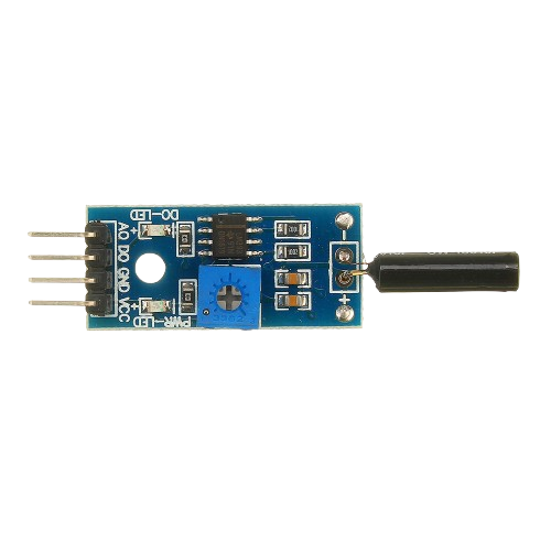
The Senser SW1801P is a compact, high-performance tilt switch designed to detect changes in orientation. It operates by closing or opening its internal contacts when tilted beyond a certain angle, making it ideal for applications requiring tilt or inclination detection. This component is widely used in safety systems, automotive devices, consumer electronics, and other applications where orientation-based triggering is essential.

Explore Projects Built with Senser SW1801P

Use Cirkit Designer to design, explore, and prototype these projects online. Some projects support real-time simulation. Click "Open Project" to start designing instantly!
ESP32-Based Smart Environmental Monitoring System with Relay Control
Image of SOCOTECO: A project utilizing Senser SW1801P in a practical application
This is a smart environmental monitoring and control system featuring an ESP32 microcontroller interfaced with a PZEM004T for power monitoring, relay modules for actuating bulbs and a fan, and an LCD for user interface. It includes flame, gas, and vibration sensors for safety monitoring purposes.
Cirkit Designer LogoOpen Project in Cirkit Designer
Battery-Powered Health Monitoring System with Nucleo WB55RG and OLED Display
Image of Pulsefex: A project utilizing Senser SW1801P in a practical application
This circuit is a multi-sensor data acquisition system that uses a Nucleo WB55RG microcontroller to interface with a digital temperature sensor (TMP102), a pulse oximeter and heart-rate sensor (MAX30102), and a 0.96" OLED display via I2C. Additionally, it includes a Sim800l module for GSM communication, powered by a 3.7V LiPo battery.
Cirkit Designer LogoOpen Project in Cirkit Designer
ESP32-Based Environmental Monitoring System with Vibration and Sound Detection
Image of DRONE CIRCUIT: A project utilizing Senser SW1801P in a practical application
This circuit features an ESP32 microcontroller connected to various sensors and output devices. A sound sensor and a SW-420 vibration sensor provide analog and digital inputs, respectively, to the ESP32 for environmental monitoring. The circuit also includes a DHT11 sensor for temperature and humidity readings, a buzzer for audible alerts, and an OLED display for visual feedback, all interfaced with the ESP32. Power is supplied by a 3.7V source connected to all components requiring VCC.
Cirkit Designer LogoOpen Project in Cirkit Designer
ESP32-Based Smart Environmental Monitoring System with Battery Power
Image of BeeHive: A project utilizing Senser SW1801P in a practical application
This circuit is a multi-sensor monitoring system powered by an ESP32 microcontroller. It includes sensors for gas (MQ135), vibration (SW-420), weight (HX711 with a load cell), and temperature/humidity (DHT22), along with a buzzer for alerts. The system is powered by a 18650 Li-ion battery managed by a TP4056 charging module.
Cirkit Designer LogoOpen Project in Cirkit Designer

Explore Projects Built with Senser SW1801P

Use Cirkit Designer to design, explore, and prototype these projects online. Some projects support real-time simulation. Click "Open Project" to start designing instantly!
Image of SOCOTECO: A project utilizing Senser SW1801P in a practical application
ESP32-Based Smart Environmental Monitoring System with Relay Control
This is a smart environmental monitoring and control system featuring an ESP32 microcontroller interfaced with a PZEM004T for power monitoring, relay modules for actuating bulbs and a fan, and an LCD for user interface. It includes flame, gas, and vibration sensors for safety monitoring purposes.
Cirkit Designer LogoOpen Project in Cirkit Designer
Image of Pulsefex: A project utilizing Senser SW1801P in a practical application
Battery-Powered Health Monitoring System with Nucleo WB55RG and OLED Display
This circuit is a multi-sensor data acquisition system that uses a Nucleo WB55RG microcontroller to interface with a digital temperature sensor (TMP102), a pulse oximeter and heart-rate sensor (MAX30102), and a 0.96" OLED display via I2C. Additionally, it includes a Sim800l module for GSM communication, powered by a 3.7V LiPo battery.
Cirkit Designer LogoOpen Project in Cirkit Designer
Image of DRONE CIRCUIT: A project utilizing Senser SW1801P in a practical application
ESP32-Based Environmental Monitoring System with Vibration and Sound Detection
This circuit features an ESP32 microcontroller connected to various sensors and output devices. A sound sensor and a SW-420 vibration sensor provide analog and digital inputs, respectively, to the ESP32 for environmental monitoring. The circuit also includes a DHT11 sensor for temperature and humidity readings, a buzzer for audible alerts, and an OLED display for visual feedback, all interfaced with the ESP32. Power is supplied by a 3.7V source connected to all components requiring VCC.
Cirkit Designer LogoOpen Project in Cirkit Designer
Image of BeeHive: A project utilizing Senser SW1801P in a practical application
ESP32-Based Smart Environmental Monitoring System with Battery Power
This circuit is a multi-sensor monitoring system powered by an ESP32 microcontroller. It includes sensors for gas (MQ135), vibration (SW-420), weight (HX711 with a load cell), and temperature/humidity (DHT22), along with a buzzer for alerts. The system is powered by a 18650 Li-ion battery managed by a TP4056 charging module.
Cirkit Designer LogoOpen Project in Cirkit Designer

Common Applications

  • Safety systems (e.g., fall detection, anti-tamper mechanisms)
  • Automotive devices (e.g., rollover detection, tilt alarms)
  • Consumer electronics (e.g., motion-activated devices, gaming controllers)
  • Industrial equipment (e.g., machinery tilt monitoring)

Technical Specifications

The following table outlines the key technical details of the Senser SW1801P:

Parameter Value
Operating Voltage 3.3V to 5V
Contact Resistance ≤ 10Ω
Insulation Resistance ≥ 10MΩ
Operating Angle 15° to 90°
Maximum Current 20mA
Operating Temperature -25°C to +85°C
Dimensions 10mm x 5mm x 5mm

Pin Configuration and Descriptions

The Senser SW1801P is a two-terminal device. Below is the pin configuration:

Pin Description
Pin 1 One terminal of the tilt switch (signal)
Pin 2 The other terminal of the tilt switch

Usage Instructions

How to Use the Senser SW1801P in a Circuit

  1. Basic Connection:

    • Connect one terminal of the SW1801P to the input pin of a microcontroller or a pull-up resistor.
    • Connect the other terminal to ground (GND).
    • When the switch is tilted, the internal contacts close, creating a low-resistance path between the two terminals.
  2. Pull-Up Resistor:

    • Use a pull-up resistor (e.g., 10kΩ) to ensure a stable high signal when the switch is not tilted.
    • The pull-up resistor connects the input pin to the supply voltage (Vcc).
  3. Debouncing:

    • The SW1801P may produce noise or multiple signals when tilting. Use a capacitor (e.g., 0.1µF) across the terminals or implement software debouncing in your microcontroller code.

Example Circuit with Arduino UNO

Below is an example of how to connect and use the Senser SW1801P with an Arduino UNO:

Circuit Diagram

  • Connections:
    • Pin 1 of SW1801P → Digital Pin 2 (Arduino)
    • Pin 2 of SW1801P → GND
    • 10kΩ pull-up resistor between Digital Pin 2 and 5V (Arduino)

Arduino Code

// Example code for using the Senser SW1801P with Arduino UNO
const int tiltSwitchPin = 2;  // Pin connected to SW1801P
const int ledPin = 13;        // Built-in LED pin for indication

void setup() {
  pinMode(tiltSwitchPin, INPUT_PULLUP); // Set tilt switch pin as input with pull-up
  pinMode(ledPin, OUTPUT);             // Set LED pin as output
  Serial.begin(9600);                  // Initialize serial communication
}

void loop() {
  int tiltState = digitalRead(tiltSwitchPin); // Read the state of the tilt switch

  if (tiltState == LOW) { // If the switch is tilted (contacts closed)
    digitalWrite(ledPin, HIGH); // Turn on the LED
    Serial.println("Tilt detected!"); // Print message to serial monitor
  } else {
    digitalWrite(ledPin, LOW); // Turn off the LED
    Serial.println("No tilt detected."); // Print message to serial monitor
  }

  delay(100); // Small delay for stability
}

Important Considerations and Best Practices

  • Orientation: Ensure the SW1801P is mounted in the correct orientation for your application.
  • Debouncing: Use hardware or software debouncing to avoid false triggers.
  • Voltage Levels: Operate the switch within its specified voltage range (3.3V to 5V).
  • Environmental Conditions: Avoid exposing the switch to extreme temperatures or moisture, as this may affect performance.

Troubleshooting and FAQs

Common Issues and Solutions

  1. No Response from the Switch:

    • Cause: Loose connections or incorrect wiring.
    • Solution: Verify all connections and ensure the pull-up resistor is properly installed.
  2. False Triggers or Noise:

    • Cause: Contact bounce or electrical noise.
    • Solution: Add a capacitor across the terminals or implement software debouncing.
  3. Switch Not Detecting Tilt:

    • Cause: Incorrect mounting orientation or insufficient tilt angle.
    • Solution: Recheck the mounting orientation and ensure the tilt angle exceeds the operating threshold (15°).

FAQs

Q1: Can the SW1801P be used with 3.3V systems?
Yes, the SW1801P operates reliably within a voltage range of 3.3V to 5V.

Q2: How do I reduce noise in the output signal?
You can reduce noise by adding a small capacitor (e.g., 0.1µF) across the switch terminals or by implementing software debouncing in your microcontroller code.

Q3: What is the maximum tilt angle the SW1801P can detect?
The SW1801P can detect tilt angles up to 90°, depending on the mounting orientation.

Q4: Is the SW1801P suitable for outdoor use?
The SW1801P is not specifically designed for outdoor use. Protect it from moisture and extreme environmental conditions to ensure reliable operation.