
How to Use Solar Charge Control: Examples, Pinouts, and Specs
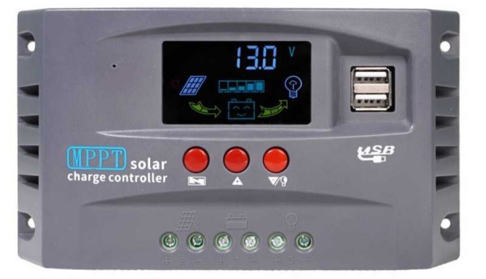
 Design with Solar Charge Control in Cirkit Designer
Introduction
A Solar Charge Controller is a device that regulates the voltage and current coming from solar panels to charge batteries efficiently. It ensures that the batteries are not overcharged, which can damage them, and prevents reverse current flow from the batteries to the solar panels during the night. Solar charge controllers are essential for maintaining the health and longevity of batteries in solar power systems.
Explore Projects Built with Solar Charge Control
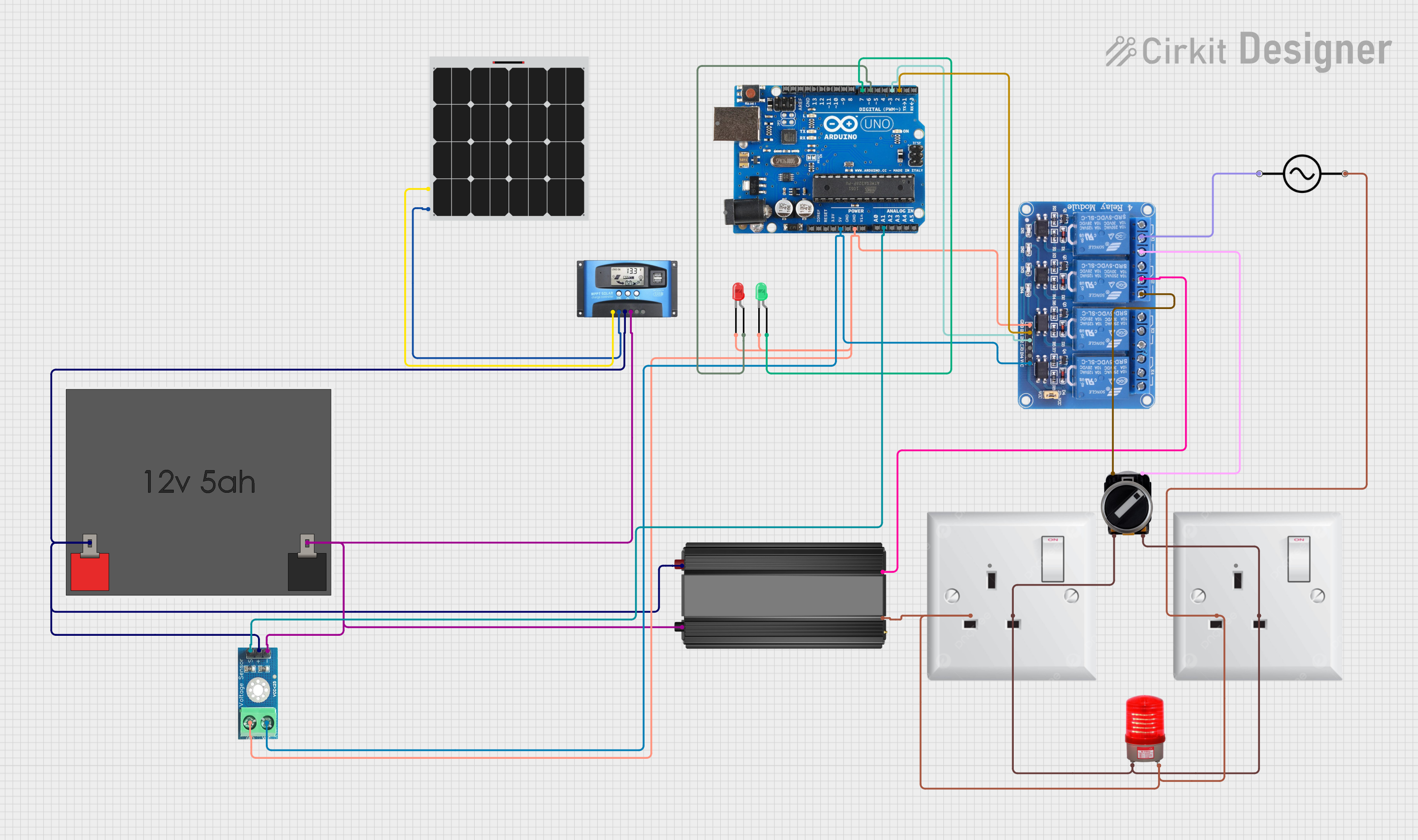 Open Project in Cirkit Designer
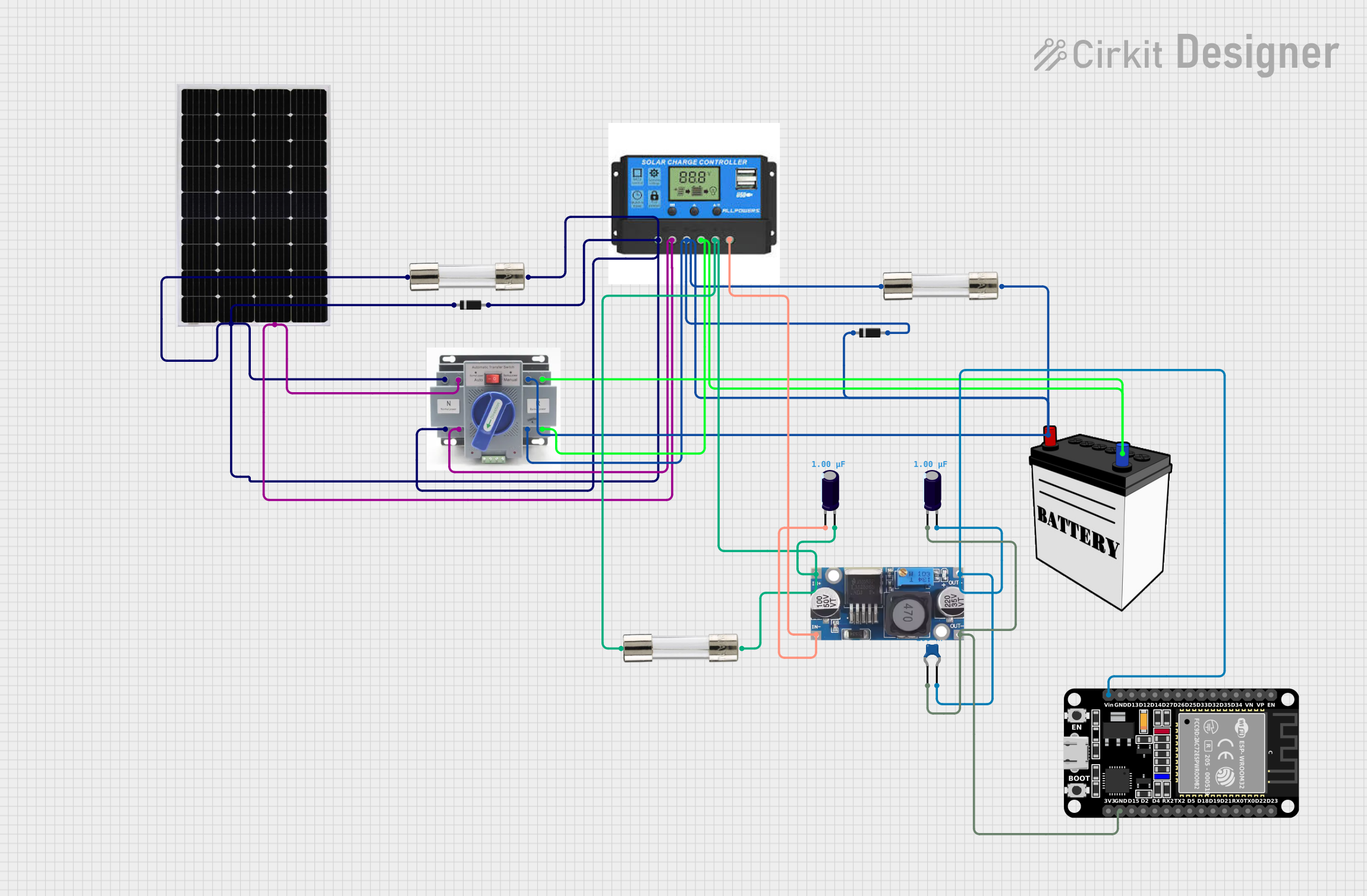 Open Project in Cirkit Designer
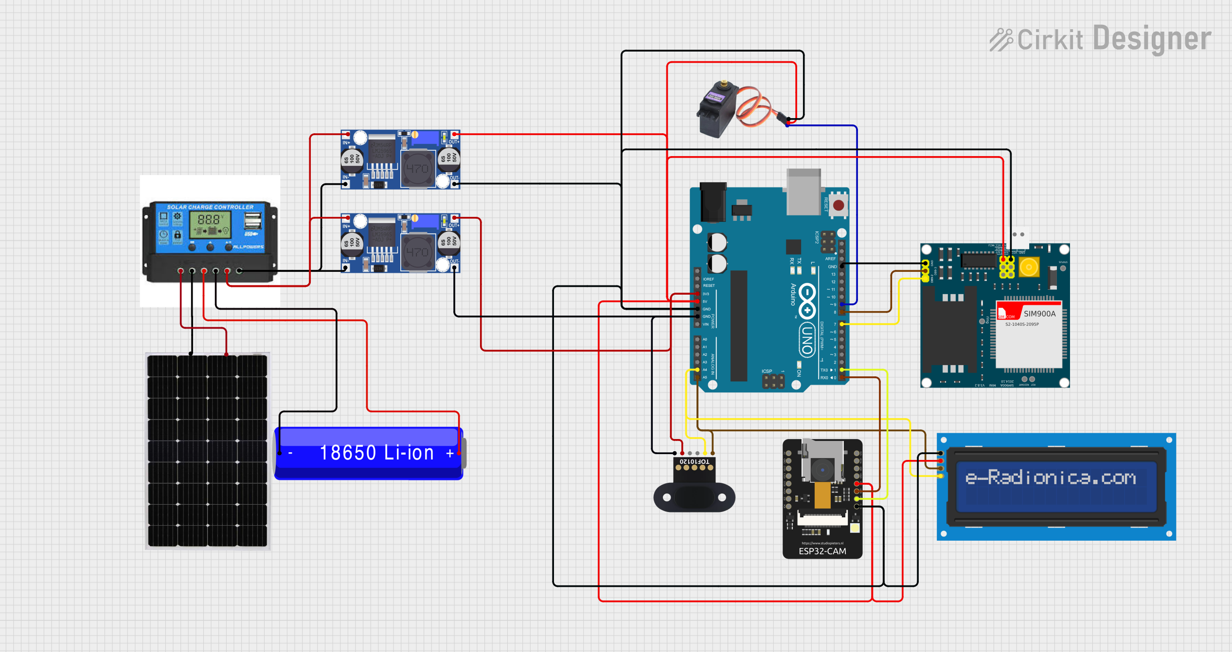 Open Project in Cirkit Designer
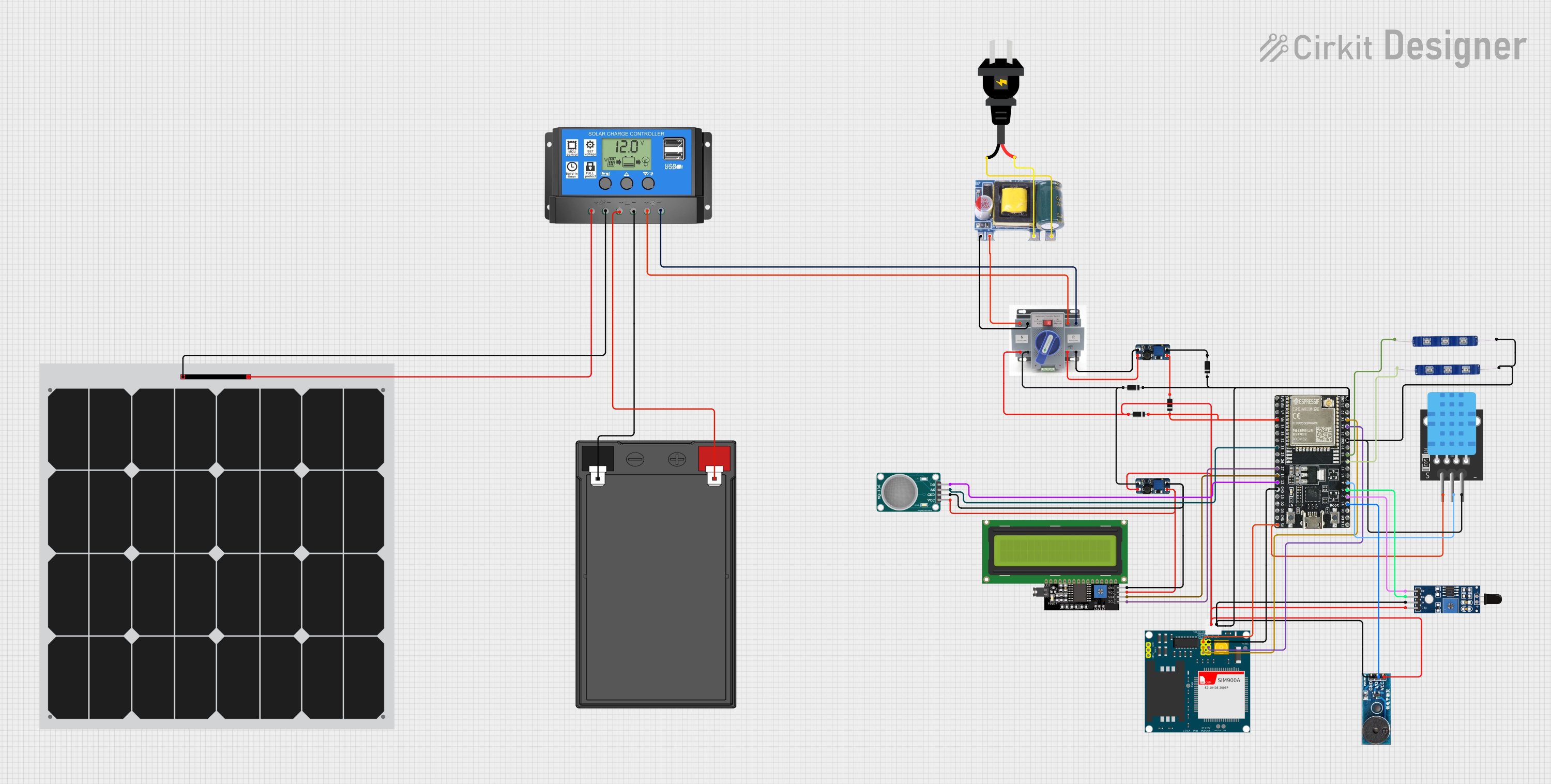 Open Project in Cirkit Designer
Explore Projects Built with Solar Charge Control
Open Project in Cirkit DesignerOpen Project in Cirkit DesignerOpen Project in Cirkit DesignerOpen Project in Cirkit DesignerCommon Applications and Use Cases
- Off-grid solar power systems
- Solar-powered lighting systems
- Solar water pumping systems
- Recreational vehicles (RVs) and boats with solar setups
- Backup power systems with solar integration
Technical Specifications
Below are the general technical specifications for a typical solar charge controller. Always refer to the datasheet of your specific model for exact details.
Key Technical Details
- Input Voltage Range: 12V to 48V (depending on the model)
- Output Voltage: Matches the battery system (e.g., 12V, 24V, or 48V)
- Maximum Input Current: 10A to 60A (varies by model)
- Efficiency: 95% to 99% (for MPPT controllers)
- Controller Type: PWM (Pulse Width Modulation) or MPPT (Maximum Power Point Tracking)
- Operating Temperature: -20°C to 60°C
- Battery Type Compatibility: Lead-acid (sealed, AGM, gel) and lithium-ion
Pin Configuration and Descriptions
The solar charge controller typically has the following terminals:
| Pin/Terminal | Label | Description |
|---|---|---|
| 1 | Solar Panel (+) | Positive terminal for connecting the solar panel. |
| 2 | Solar Panel (-) | Negative terminal for connecting the solar panel. |
| 3 | Battery (+) | Positive terminal for connecting the battery. |
| 4 | Battery (-) | Negative terminal for connecting the battery. |
| 5 | Load (+) | Positive terminal for connecting the DC load (optional, depending on the model). |
| 6 | Load (-) | Negative terminal for connecting the DC load (optional, depending on the model). |
Usage Instructions
How to Use the Component in a Circuit
Connect the Battery First:
- Connect the positive and negative terminals of the battery to the corresponding
Battery (+)andBattery (-)terminals on the charge controller. - This step is crucial as it allows the controller to detect the battery voltage and configure itself accordingly.
- Connect the positive and negative terminals of the battery to the corresponding
Connect the Solar Panel:
- Connect the positive and negative terminals of the solar panel to the
Solar Panel (+)andSolar Panel (-)terminals. - Ensure the solar panel is not exposed to sunlight during this step to avoid live voltage.
- Connect the positive and negative terminals of the solar panel to the
Connect the Load (Optional):
- If your charge controller supports load output, connect the DC load to the
Load (+)andLoad (-)terminals. - This output is typically used for small DC appliances or lighting systems.
- If your charge controller supports load output, connect the DC load to the
Power On:
- Once all connections are secure, expose the solar panel to sunlight. The charge controller will begin regulating the power flow to the battery.
Important Considerations and Best Practices
- Battery Type Selection: Ensure the charge controller is configured for the correct battery type (e.g., lead-acid or lithium-ion).
- Wire Sizing: Use appropriately sized wires to handle the current without overheating or voltage drops.
- Fuses and Protection: Install fuses or circuit breakers between the solar panel, battery, and charge controller for safety.
- Ventilation: Place the charge controller in a well-ventilated area to prevent overheating.
- Avoid Reverse Polarity: Double-check all connections to avoid damaging the controller or other components.
Arduino UNO Integration Example
If you want to monitor the battery voltage using an Arduino UNO, you can connect the battery terminals to an analog input pin via a voltage divider circuit. Below is an example code snippet:
// Arduino code to monitor battery voltage using a voltage divider
const int batteryPin = A0; // Analog pin connected to the voltage divider
const float voltageDividerRatio = 5.7; // Adjust based on your resistor values
const float referenceVoltage = 5.0; // Arduino's reference voltage (5V for UNO)

void setup() {
  Serial.begin(9600); // Initialize serial communication
}

void loop() {
  int analogValue = analogRead(batteryPin); // Read the analog input
  float batteryVoltage = (analogValue / 1023.0) * referenceVoltage * voltageDividerRatio;

  // Print the battery voltage to the Serial Monitor
  Serial.print("Battery Voltage: ");
  Serial.print(batteryVoltage);
  Serial.println(" V");

  delay(1000); // Wait for 1 second before the next reading
}
Note: Use a voltage divider circuit to step down the battery voltage to a safe range for the Arduino's analog input (0-5V). Choose resistor values accordingly.
Troubleshooting and FAQs
Common Issues Users Might Face
No Power Output from the Controller:
- Cause: Incorrect wiring or loose connections.
- Solution: Double-check all connections and ensure proper polarity.
Battery Not Charging:
- Cause: Insufficient sunlight, faulty solar panel, or damaged battery.
- Solution: Test the solar panel output with a multimeter and inspect the battery health.
Overheating of the Controller:
- Cause: Poor ventilation or excessive current.
- Solution: Ensure the controller is installed in a well-ventilated area and verify the current rating.
Load Output Not Working:
- Cause: Load exceeds the controller's capacity or incorrect settings.
- Solution: Check the load rating and ensure it is within the controller's limits.
Solutions and Tips for Troubleshooting
- Check LED Indicators: Most controllers have LED indicators or an LCD screen to display system status and errors.
- Use a Multimeter: Measure the voltage and current at various points in the circuit to identify issues.
- Consult the Manual: Refer to the specific charge controller's user manual for detailed troubleshooting steps.
By following this documentation, you can effectively use a solar charge controller to manage your solar power system and ensure optimal performance.