How to Use ADC IC: Examples, Pinouts, and Specs
Introduction
The AD7606 is a high-performance, 16-bit Analog-to-Digital Converter (ADC) IC manufactured by Analog Devices. It is designed to convert analog signals into precise digital data, enabling seamless integration of real-world signals into digital systems. The AD7606 features simultaneous sampling of up to 8 input channels, making it ideal for applications requiring high accuracy and speed.
Explore Projects Built with ADC IC

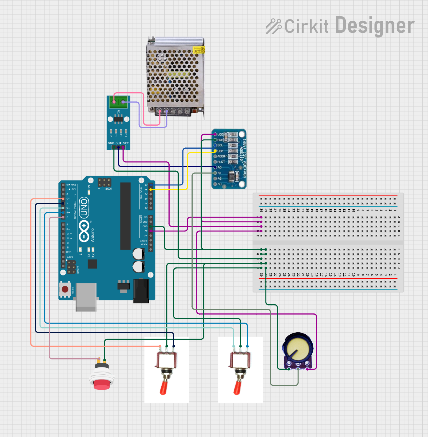
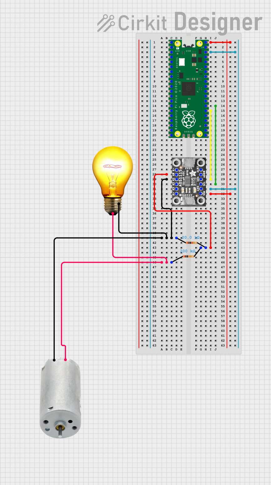

Explore Projects Built with ADC IC
Common Applications and Use Cases
- Data acquisition systems
- Industrial process control
- Power quality monitoring
- Medical instrumentation
- Motor control systems
- Audio signal processing
Technical Specifications
The AD7606 is a versatile ADC IC with the following key technical specifications:
| Parameter | Value |
|---|---|
| Resolution | 16-bit |
| Number of Input Channels | 8 |
| Input Voltage Range | ±10 V, ±5 V (software-selectable) |
| Sampling Rate | Up to 200 kSPS per channel |
| Power Supply Voltage | 5 V (analog) / 3.3 V (digital) |
| Input Impedance | 1 MΩ |
| Interface | Parallel / Serial (SPI) |
| Operating Temperature Range | -40°C to +85°C |
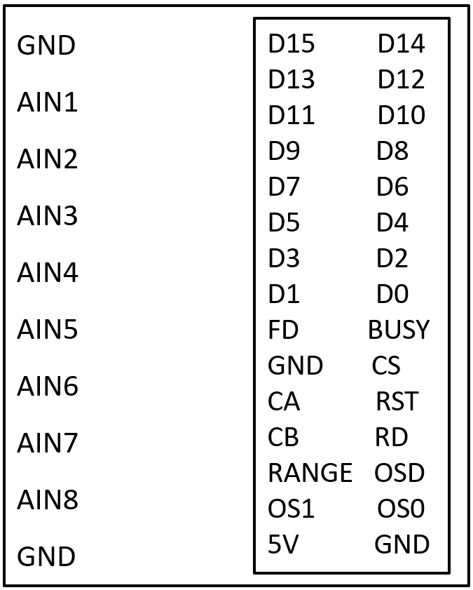
Pin Configuration and Descriptions
The AD7606 is available in a 64-lead LQFP package. Below is a summary of the key pins:
| Pin Name | Pin Number | Description |
|---|---|---|
| VDD | 1, 2 | Analog power supply (5 V). |
| VSS | 3, 4 | Analog ground. |
| REFIN/REFOUT | 5 | Reference input/output pin. |
| VINx (x=1-8) | 6-13 | Analog input channels (up to 8). |
| BUSY | 14 | Indicates conversion status (active high during conversion). |
| CS | 15 | Chip select (active low). |
| RD | 16 | Read data signal (active low). |
| WR | 17 | Write signal for configuration (active low). |
| DB[0:15] | 18-33 | Parallel data bus for digital output. |
| SCLK | 34 | Serial clock for SPI interface. |
| DOUTA/DOUTB | 35, 36 | Serial data output channels for SPI interface. |
| RESET | 37 | Resets the ADC to its default state (active low). |
| RANGE | 38 | Selects input voltage range (±10 V or ±5 V). |
| AVCC | 39 | Digital power supply (3.3 V). |
| AGND | 40 | Digital ground. |
For a complete pinout, refer to the official datasheet provided by Analog Devices.
Usage Instructions
How to Use the AD7606 in a Circuit
- Power Supply: Connect the analog power supply (VDD) to 5 V and the digital power supply (AVCC) to 3.3 V. Ensure proper decoupling capacitors are placed near the power pins.
- Input Configuration: Connect the analog input signals to the VINx pins. Use the RANGE pin to select the desired input voltage range (±10 V or ±5 V).
- Reference Voltage: Use the internal reference (REFOUT) or connect an external reference voltage to the REFIN pin.
- Interface Selection: Choose between the parallel or serial (SPI) interface for data communication. Configure the necessary pins (e.g., DB[0:15] for parallel or SCLK/DOUTA for SPI).
- Data Acquisition:
- Initiate a conversion by toggling the WR pin.
- Monitor the BUSY pin to determine when the conversion is complete.
- Read the digital output data via the selected interface (parallel or SPI).
Important Considerations and Best Practices
- Input Signal Conditioning: Use appropriate filters to remove noise from the input signals before feeding them into the ADC.
- Grounding: Ensure proper grounding to minimize noise and interference. Use separate analog and digital ground planes if possible.
- Decoupling: Place decoupling capacitors close to the power supply pins to stabilize the voltage supply.
- Reset: Always reset the ADC using the RESET pin after power-up to ensure proper initialization.
- Clock Configuration: For SPI communication, ensure the SCLK frequency does not exceed the maximum supported by the AD7606.
Example: Interfacing AD7606 with Arduino UNO (SPI Mode)
Below is an example code snippet for interfacing the AD7606 with an Arduino UNO using the SPI interface:
#include <SPI.h>

// Pin definitions
#define CS_PIN 10  // Chip Select pin
#define RESET_PIN 9 // Reset pin
#define BUSY_PIN 8  // Busy pin

void setup() {
  // Initialize SPI
  SPI.begin();
  SPI.setClockDivider(SPI_CLOCK_DIV16); // Set SPI clock speed
  SPI.setDataMode(SPI_MODE0);           // SPI mode 0
  pinMode(CS_PIN, OUTPUT);
  pinMode(RESET_PIN, OUTPUT);
  pinMode(BUSY_PIN, INPUT);

  // Reset the AD7606
  digitalWrite(RESET_PIN, LOW);
  delay(10); // Hold reset low for 10 ms
  digitalWrite(RESET_PIN, HIGH);

  // Configure the ADC
  digitalWrite(CS_PIN, HIGH); // Deselect the ADC
}

void loop() {
  // Start a conversion
  digitalWrite(CS_PIN, LOW); // Select the ADC
  SPI.transfer(0x00);        // Send a dummy byte to initiate conversion
  digitalWrite(CS_PIN, HIGH); // Deselect the ADC

  // Wait for conversion to complete
  while (digitalRead(BUSY_PIN) == HIGH);

  // Read data from the ADC
  digitalWrite(CS_PIN, LOW); // Select the ADC
  uint16_t data = SPI.transfer(0x00) << 8; // Read MSB
  data |= SPI.transfer(0x00);              // Read LSB
  digitalWrite(CS_PIN, HIGH); // Deselect the ADC

  // Print the result
  Serial.println(data);

  delay(1000); // Wait 1 second before the next conversion
}
Troubleshooting and FAQs
Common Issues and Solutions
No Output Data:
- Ensure the power supply voltages (VDD and AVCC) are within the specified range.
- Verify that the RESET pin is toggled after power-up.
- Check the SPI or parallel interface connections and configurations.
Incorrect Conversion Results:
- Verify the input signal is within the selected voltage range (±10 V or ±5 V).
- Check for noise or interference in the input signal. Use proper filtering if necessary.
- Ensure the reference voltage is stable and accurate.
BUSY Pin Stuck High:
- Confirm that the WR pin is toggled correctly to start a conversion.
- Check for any short circuits or incorrect wiring.
FAQs
Q1: Can I use the AD7606 with a 3.3 V analog power supply?
A1: No, the AD7606 requires a 5 V analog power supply (VDD). However, the digital power supply (AVCC) operates at 3.3 V.
Q2: What is the maximum sampling rate of the AD7606?
A2: The AD7606 supports a maximum sampling rate of 200 kSPS per channel.
Q3: Can I use the AD7606 in noisy environments?
A3: Yes, but it is recommended to use proper input signal conditioning (e.g., filters) and grounding techniques to minimize noise.
Q4: Does the AD7606 support differential input signals?
A4: No, the AD7606 is designed for single-ended input signals.
For further details, refer to the official datasheet provided by Analog Devices.