Cirkit Designer Logo
Cirkit Designer
Your all-in-one circuit design IDE
Home / 
Component Documentation

How to Use 28BYJ-48 Motor Driver: Examples, Pinouts, and Specs

Image of 28BYJ-48 Motor Driver
Cirkit Designer LogoDesign with 28BYJ-48 Motor Driver in Cirkit Designer

Introduction

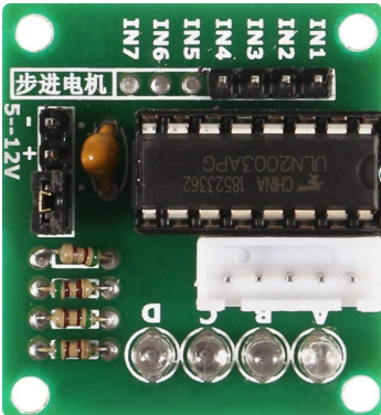
The 28BYJ-48 Motor Driver is a compact and efficient driver module designed to control the 28BYJ-48 stepper motor. This driver enables precise control of the motor's rotation and position, making it ideal for applications requiring accurate movement. It is commonly used in robotics, automation systems, 3D printers, and other projects where stepper motors are employed. The driver is typically paired with microcontrollers, such as Arduino, for seamless integration and control.

Explore Projects Built with 28BYJ-48 Motor Driver

Use Cirkit Designer to design, explore, and prototype these projects online. Some projects support real-time simulation. Click "Open Project" to start designing instantly!
Arduino Mega 2560-Controlled Stepper Motors with RFID Access and Traffic Light Indication
Image of Copy of test: A project utilizing 28BYJ-48 Motor Driver in a practical application
This circuit controls two 28BYJ-48 stepper motors using A4988 stepper motor driver carriers, interfaced with an Arduino Mega 2560 microcontroller. It features an RFID-RC522 module for RFID reading, a 16x4 LCD display with I2C interface for user interaction, and a piezo speaker for audio feedback. Additionally, there is a traffic light module controlled by the Arduino, and a 48V to 5V converter to step down voltage for the logic levels. The power supply provides 12V to the motor drivers and is connected to a standard power outlet.
Cirkit Designer LogoOpen Project in Cirkit Designer
RFID-Activated Traffic Light Controller with Auditory Feedback Using Arduino Mega
Image of test: A project utilizing 28BYJ-48 Motor Driver in a practical application
This circuit is designed to control two 28BYJ-48 stepper motors using A4988 stepper motor driver carriers, with an Arduino Mega 2560 as the central microcontroller. It includes an RFID-RC522 module for RFID reading, an LCD display for user interface, and a traffic light and piezo speaker for visual and audio signaling. The circuit is powered by a 12V 5A power supply, which is stepped down to 5V for logic level components, and it interfaces with a power outlet for AC to DC conversion.
Cirkit Designer LogoOpen Project in Cirkit Designer
Arduino UNO Wi-Fi Controlled DC Motor Driver with Battery Management System
Image of RC Ball: A project utilizing 28BYJ-48 Motor Driver in a practical application
This circuit is a motor control system powered by a 3s 20A BMS and 18650 Li-ion batteries, which drives two DC Mini Metal Gear Motors using an L298N motor driver. The Arduino UNO R4 WiFi microcontroller is used to control the motor driver, and a buck converter provides regulated power to a Type-C port.
Cirkit Designer LogoOpen Project in Cirkit Designer
Battery-Powered Line Following Robot with L298N Motor Driver and KY-033 Sensors
Image of obstacle-avoiding robot: A project utilizing 28BYJ-48 Motor Driver in a practical application
This circuit is designed to control a two-wheeled robot using an L298N motor driver, powered by two 18650 Li-ion batteries. It includes two KY-033 line tracking sensors for navigation and a 74HC04 inverter to process sensor signals and control the motor driver inputs.
Cirkit Designer LogoOpen Project in Cirkit Designer

Explore Projects Built with 28BYJ-48 Motor Driver

Use Cirkit Designer to design, explore, and prototype these projects online. Some projects support real-time simulation. Click "Open Project" to start designing instantly!
Image of Copy of test: A project utilizing 28BYJ-48 Motor Driver in a practical application
Arduino Mega 2560-Controlled Stepper Motors with RFID Access and Traffic Light Indication
This circuit controls two 28BYJ-48 stepper motors using A4988 stepper motor driver carriers, interfaced with an Arduino Mega 2560 microcontroller. It features an RFID-RC522 module for RFID reading, a 16x4 LCD display with I2C interface for user interaction, and a piezo speaker for audio feedback. Additionally, there is a traffic light module controlled by the Arduino, and a 48V to 5V converter to step down voltage for the logic levels. The power supply provides 12V to the motor drivers and is connected to a standard power outlet.
Cirkit Designer LogoOpen Project in Cirkit Designer
Image of test: A project utilizing 28BYJ-48 Motor Driver in a practical application
RFID-Activated Traffic Light Controller with Auditory Feedback Using Arduino Mega
This circuit is designed to control two 28BYJ-48 stepper motors using A4988 stepper motor driver carriers, with an Arduino Mega 2560 as the central microcontroller. It includes an RFID-RC522 module for RFID reading, an LCD display for user interface, and a traffic light and piezo speaker for visual and audio signaling. The circuit is powered by a 12V 5A power supply, which is stepped down to 5V for logic level components, and it interfaces with a power outlet for AC to DC conversion.
Cirkit Designer LogoOpen Project in Cirkit Designer
Image of RC Ball: A project utilizing 28BYJ-48 Motor Driver in a practical application
Arduino UNO Wi-Fi Controlled DC Motor Driver with Battery Management System
This circuit is a motor control system powered by a 3s 20A BMS and 18650 Li-ion batteries, which drives two DC Mini Metal Gear Motors using an L298N motor driver. The Arduino UNO R4 WiFi microcontroller is used to control the motor driver, and a buck converter provides regulated power to a Type-C port.
Cirkit Designer LogoOpen Project in Cirkit Designer
Image of obstacle-avoiding robot: A project utilizing 28BYJ-48 Motor Driver in a practical application
Battery-Powered Line Following Robot with L298N Motor Driver and KY-033 Sensors
This circuit is designed to control a two-wheeled robot using an L298N motor driver, powered by two 18650 Li-ion batteries. It includes two KY-033 line tracking sensors for navigation and a 74HC04 inverter to process sensor signals and control the motor driver inputs.
Cirkit Designer LogoOpen Project in Cirkit Designer

Technical Specifications

The 28BYJ-48 Motor Driver is often based on the ULN2003 Darlington transistor array, which provides the necessary current amplification to drive the stepper motor. Below are the key technical details:

Key Specifications

Parameter Value
Operating Voltage 5V DC
Maximum Output Current 500 mA per channel
Number of Output Channels 4
Step Resolution Full-step and Half-step modes
Compatible Motor 28BYJ-48 Stepper Motor
Dimensions ~31mm x 35mm

Pin Configuration and Descriptions

The 28BYJ-48 Motor Driver typically has a 10-pin header for motor and power connections. Below is the pinout:

Pin Number Label Description
1 IN1 Input signal for coil A
2 IN2 Input signal for coil B
3 IN3 Input signal for coil C
4 IN4 Input signal for coil D
5 VCC Power supply input (5V DC)
6 GND Ground connection
7-10 Motor Pins Connects to the 28BYJ-48 stepper motor coils

Usage Instructions

How to Use the Component in a Circuit

  1. Power Supply: Connect the VCC pin to a 5V DC power source and the GND pin to the ground.
  2. Motor Connection: Attach the 4-pin connector of the 28BYJ-48 stepper motor to the motor pins on the driver module.
  3. Microcontroller Interface: Connect the IN1, IN2, IN3, and IN4 pins to the digital output pins of a microcontroller (e.g., Arduino).
  4. Programming: Use a stepper motor library or write custom code to control the motor's steps and direction.

Important Considerations and Best Practices

  • Power Supply: Ensure the power supply can provide sufficient current for the motor and driver.
  • Heat Dissipation: Avoid prolonged operation at high currents to prevent overheating.
  • Step Sequence: Use the correct step sequence (full-step or half-step) to avoid motor misalignment.
  • Decoupling Capacitor: Add a decoupling capacitor (e.g., 100 µF) across the VCC and GND pins to stabilize the power supply.

Example Code for Arduino UNO

Below is an example code to control the 28BYJ-48 stepper motor using the Arduino UNO:

#include <Stepper.h>

// Define the number of steps per revolution for the 28BYJ-48 motor
#define STEPS_PER_REV 2048

// Initialize the Stepper library with the motor's step sequence pins
Stepper stepper(STEPS_PER_REV, 8, 10, 9, 11);

void setup() {
  // Set the motor speed (in RPM)
  stepper.setSpeed(10); // 10 RPM
  Serial.begin(9600);
  Serial.println("28BYJ-48 Stepper Motor Test");
}

void loop() {
  // Rotate the motor 1 revolution clockwise
  Serial.println("Rotating clockwise...");
  stepper.step(STEPS_PER_REV);
  delay(1000); // Wait for 1 second

  // Rotate the motor 1 revolution counterclockwise
  Serial.println("Rotating counterclockwise...");
  stepper.step(-STEPS_PER_REV);
  delay(1000); // Wait for 1 second
}

Note: Ensure the pins in the Stepper constructor match the connections to the motor driver (e.g., pins 8, 10, 9, and 11 in this example).

Troubleshooting and FAQs

Common Issues and Solutions

  1. Motor Not Moving:

    • Cause: Incorrect wiring or loose connections.
    • Solution: Double-check all connections between the motor, driver, and microcontroller.
  2. Motor Vibrates but Does Not Rotate:

    • Cause: Incorrect step sequence or insufficient power supply.
    • Solution: Verify the step sequence in the code and ensure the power supply provides adequate current.
  3. Overheating Driver:

    • Cause: Prolonged operation at high current.
    • Solution: Reduce the motor speed or add a heat sink to the driver.
  4. Erratic Motor Movement:

    • Cause: Electrical noise or unstable power supply.
    • Solution: Add a decoupling capacitor across the VCC and GND pins.

FAQs

  • Q: Can I use a 12V power supply with the 28BYJ-48 Motor Driver?
    A: No, the driver is designed for 5V operation. Using a higher voltage may damage the driver or motor.

  • Q: How do I increase the torque of the 28BYJ-48 motor?
    A: You can increase the torque by reducing the motor speed or using a higher current-rated driver.

  • Q: Can I control multiple motors with one Arduino?
    A: Yes, you can control multiple motors by using additional motor drivers and assigning separate pins for each driver.

This documentation provides a comprehensive guide to using the 28BYJ-48 Motor Driver effectively in your projects.