Cirkit Designer Logo
Cirkit Designer
Your all-in-one circuit design IDE
Home / 
Component Documentation

How to Use USB-6210: Examples, Pinouts, and Specs

Image of USB-6210
Cirkit Designer LogoDesign with USB-6210 in Cirkit Designer

Introduction

The NI USB-6210 is a multifunction data acquisition (DAQ) device manufactured by National Instruments. It connects to a computer via USB and provides a versatile platform for acquiring, generating, and processing signals. The USB-6210 features analog input channels, digital I/O lines, and counter/timer capabilities, making it ideal for a wide range of measurement and control applications.

Explore Projects Built with USB-6210

Use Cirkit Designer to design, explore, and prototype these projects online. Some projects support real-time simulation. Click "Open Project" to start designing instantly!
Laptop-Connected Adalm Pluto SDR with Dual Antennas
Image of Zidan Project: A project utilizing USB-6210 in a practical application
This circuit connects an Adalm Pluto Software Defined Radio (SDR) to a laptop via a Type-B to USB cable, allowing the laptop to control the SDR and process signals. Additionally, two antennas are connected to the Adalm Pluto SDR, which are likely used for transmitting and receiving radio signals as part of the SDR's functionality.
Cirkit Designer LogoOpen Project in Cirkit Designer
Beelink Mini S12 N95 and Arduino UNO Based Fingerprint Authentication System with ESP32 CAM
Image of design 3: A project utilizing USB-6210 in a practical application
This circuit features a Beelink MINI S12 N95 computer connected to a 7-inch display via HDMI for video output and two USB connections for power and touch screen functionality. An Arduino UNO is interfaced with a fingerprint scanner for biometric input. The Beelink MINI S12 N95 is powered by a PC power supply, which in turn is connected to a 240V power source. Additionally, an ESP32 CAM module is powered and programmed via a USB plug and an FTDI programmer, respectively, for wireless camera capabilities.
Cirkit Designer LogoOpen Project in Cirkit Designer
Arduino Mega 2560 Based Security System with Fingerprint Authentication and SMS Alerts
Image of Door security system: A project utilizing USB-6210 in a practical application
This circuit features an Arduino Mega 2560 microcontroller interfaced with a SIM800L GSM module, two fingerprint scanners, an I2C LCD display, an IR sensor, and a piezo buzzer. Power management is handled by a PowerBoost 1000 Basic Pad USB, a TP4056 charging module, and a Li-ion 18650 battery, with an option to use a Mini AC-DC 110V-230V to 5V 700mA module for direct power supply. The primary functionality appears to be a security system with GSM communication capabilities, biometric access control, and visual/audible feedback.
Cirkit Designer LogoOpen Project in Cirkit Designer
Cellular-Enabled IoT Device with Real-Time Clock and Power Management
Image of LRCM PHASE 2 BASIC: A project utilizing USB-6210 in a practical application
This circuit features a LilyGo-SIM7000G module for cellular communication and GPS functionality, interfaced with an RTC DS3231 for real-time clock capabilities. It includes voltage sensing through two voltage sensor modules, and uses an 8-channel opto-coupler for isolating different parts of the circuit. Power management is handled by a buck converter connected to a DC power source and batteries, with a fuse for protection and a rocker switch for on/off control. Additionally, there's an LED for indication purposes.
Cirkit Designer LogoOpen Project in Cirkit Designer

Explore Projects Built with USB-6210

Use Cirkit Designer to design, explore, and prototype these projects online. Some projects support real-time simulation. Click "Open Project" to start designing instantly!
Image of Zidan Project: A project utilizing USB-6210 in a practical application
Laptop-Connected Adalm Pluto SDR with Dual Antennas
This circuit connects an Adalm Pluto Software Defined Radio (SDR) to a laptop via a Type-B to USB cable, allowing the laptop to control the SDR and process signals. Additionally, two antennas are connected to the Adalm Pluto SDR, which are likely used for transmitting and receiving radio signals as part of the SDR's functionality.
Cirkit Designer LogoOpen Project in Cirkit Designer
Image of design 3: A project utilizing USB-6210 in a practical application
Beelink Mini S12 N95 and Arduino UNO Based Fingerprint Authentication System with ESP32 CAM
This circuit features a Beelink MINI S12 N95 computer connected to a 7-inch display via HDMI for video output and two USB connections for power and touch screen functionality. An Arduino UNO is interfaced with a fingerprint scanner for biometric input. The Beelink MINI S12 N95 is powered by a PC power supply, which in turn is connected to a 240V power source. Additionally, an ESP32 CAM module is powered and programmed via a USB plug and an FTDI programmer, respectively, for wireless camera capabilities.
Cirkit Designer LogoOpen Project in Cirkit Designer
Image of Door security system: A project utilizing USB-6210 in a practical application
Arduino Mega 2560 Based Security System with Fingerprint Authentication and SMS Alerts
This circuit features an Arduino Mega 2560 microcontroller interfaced with a SIM800L GSM module, two fingerprint scanners, an I2C LCD display, an IR sensor, and a piezo buzzer. Power management is handled by a PowerBoost 1000 Basic Pad USB, a TP4056 charging module, and a Li-ion 18650 battery, with an option to use a Mini AC-DC 110V-230V to 5V 700mA module for direct power supply. The primary functionality appears to be a security system with GSM communication capabilities, biometric access control, and visual/audible feedback.
Cirkit Designer LogoOpen Project in Cirkit Designer
Image of LRCM PHASE 2 BASIC: A project utilizing USB-6210 in a practical application
Cellular-Enabled IoT Device with Real-Time Clock and Power Management
This circuit features a LilyGo-SIM7000G module for cellular communication and GPS functionality, interfaced with an RTC DS3231 for real-time clock capabilities. It includes voltage sensing through two voltage sensor modules, and uses an 8-channel opto-coupler for isolating different parts of the circuit. Power management is handled by a buck converter connected to a DC power source and batteries, with a fuse for protection and a rocker switch for on/off control. Additionally, there's an LED for indication purposes.
Cirkit Designer LogoOpen Project in Cirkit Designer

Common Applications and Use Cases

  • Data logging and signal monitoring
  • Sensor interfacing and measurement
  • Industrial automation and control systems
  • Laboratory experiments and research
  • Prototyping and testing of electronic circuits

Technical Specifications

Key Technical Details

Parameter Specification
Analog Inputs 16 single-ended or 8 differential channels
Input Resolution 16 bits
Input Range ±10 V, ±5 V, ±2 V, ±1 V (software-selectable)
Sampling Rate Up to 250 kS/s (aggregate)
Digital I/O Lines 4 bidirectional lines
Counter/Timers 2 counters (32-bit resolution)
Connectivity USB 2.0
Power Supply USB bus-powered
Operating Temperature 0 °C to 45 °C
Dimensions 16.9 cm × 10.6 cm × 3.6 cm

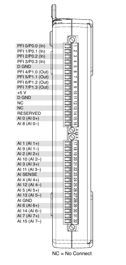
Pin Configuration and Descriptions

The USB-6210 features a 68-pin connector for interfacing with external devices. Below is a summary of the pin configuration:

Analog Input Channels

Pin Number Signal Name Description
1-16 AI <0..15> Analog input channels (single-ended)
17-32 AI GND Analog input ground

Digital I/O Lines

Pin Number Signal Name Description
33-36 DIO <0..3> Digital input/output lines
37-40 DIO GND Digital I/O ground

Counter/Timer Signals

Pin Number Signal Name Description
41 CTR 0 OUT Counter 0 output
42 CTR 0 GATE Counter 0 gate
43 CTR 1 OUT Counter 1 output
44 CTR 1 GATE Counter 1 gate

Power and Ground

Pin Number Signal Name Description
67 +5V +5V power output (USB-powered)
68 GND Ground

Usage Instructions

How to Use the USB-6210 in a Circuit

  1. Connect the Device to a Computer: Use a USB cable to connect the USB-6210 to a computer. Ensure the appropriate drivers and software (e.g., NI-DAQmx) are installed.
  2. Configure the Device: Use the NI Measurement & Automation Explorer (MAX) to configure the device, set up channels, and define input/output parameters.
  3. Connect External Signals: Wire sensors, actuators, or other devices to the appropriate pins on the 68-pin connector. Use the pin configuration tables above as a reference.
  4. Acquire or Generate Signals: Use software such as LabVIEW, MATLAB, or Python (with NI-DAQmx library) to programmatically acquire or generate signals.

Important Considerations and Best Practices

  • Signal Conditioning: Ensure proper signal conditioning (e.g., filtering, amplification) for accurate measurements.
  • Grounding: Connect all grounds (AI GND, DIO GND) properly to avoid noise and ground loops.
  • Input Voltage Limits: Do not exceed the specified input voltage range to prevent damage to the device.
  • Sampling Rate: Distribute the aggregate sampling rate across all active channels when using multiple analog inputs.

Example Code for Arduino UNO Integration

Although the USB-6210 is typically used with a computer, it can interface with an Arduino UNO for digital I/O purposes. Below is an example of how to send digital signals from the Arduino to the USB-6210:

// Example: Sending digital signals from Arduino to USB-6210
// This code toggles a digital output pin on the Arduino, which can be read
// by the USB-6210 as a digital input.

const int outputPin = 7; // Arduino pin connected to USB-6210 DIO <0>

void setup() {
  pinMode(outputPin, OUTPUT); // Set the pin as an output
}

void loop() {
  digitalWrite(outputPin, HIGH); // Set the pin HIGH
  delay(500); // Wait for 500 ms
  digitalWrite(outputPin, LOW); // Set the pin LOW
  delay(500); // Wait for 500 ms
}

Troubleshooting and FAQs

Common Issues and Solutions

  1. Device Not Recognized by Computer

    • Cause: Missing or outdated drivers.
    • Solution: Install or update the NI-DAQmx driver from the National Instruments website.
  2. Incorrect or No Signal Readings

    • Cause: Improper wiring or configuration.
    • Solution: Verify connections and ensure the correct input range and channel settings in the software.
  3. Noise in Analog Signals

    • Cause: Ground loops or unshielded cables.
    • Solution: Use shielded cables and ensure proper grounding.
  4. Overvoltage Damage

    • Cause: Input voltage exceeds the specified range.
    • Solution: Use voltage dividers or limiters to protect the inputs.

FAQs

Q: Can the USB-6210 be used with LabVIEW?
A: Yes, the USB-6210 is fully compatible with LabVIEW and can be programmed using the NI-DAQmx driver.

Q: What is the maximum sampling rate for a single channel?
A: The maximum sampling rate for a single channel is 250 kS/s.

Q: Can the USB-6210 output analog signals?
A: No, the USB-6210 does not have analog output capabilities. It only supports analog input, digital I/O, and counters.

Q: Is external power required for the USB-6210?
A: No, the USB-6210 is powered directly via the USB connection.