How to Use LIS331HH: Examples, Pinouts, and Specs

Introduction
The LIS331HH is a low-power, three-axis accelerometer designed for motion sensing applications. It provides digital output via I2C or SPI interfaces, making it versatile and easy to integrate into a variety of systems. With its high sensitivity and wide measurement range, the LIS331HH is ideal for applications such as vibration monitoring, tilt sensing, and motion detection in consumer electronics, industrial equipment, and robotics.
Explore Projects Built with LIS331HH
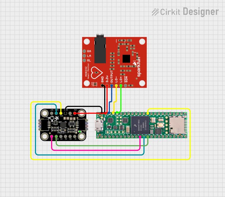


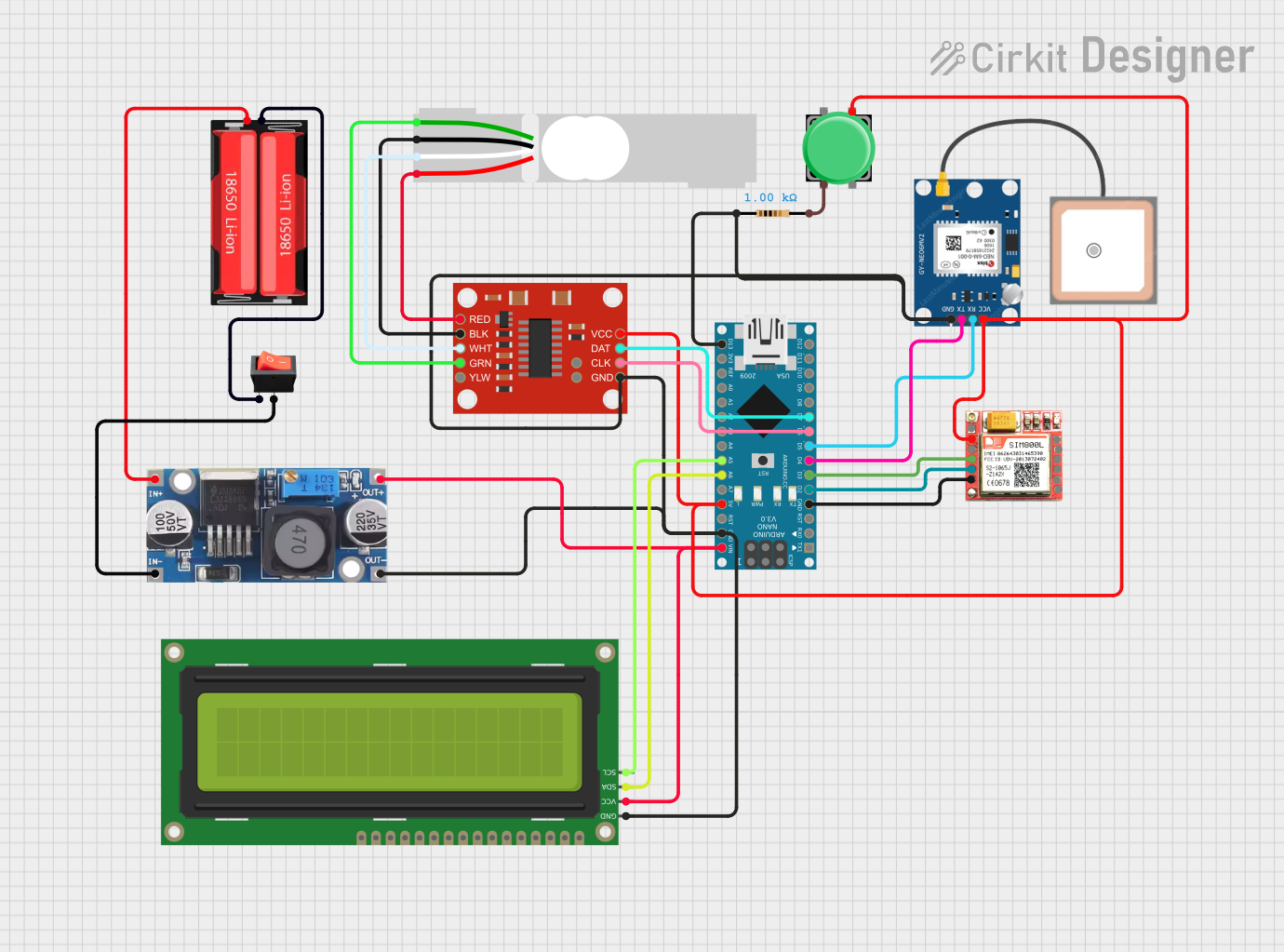
Explore Projects Built with LIS331HH
Common Applications
- Motion detection in smartphones and wearables
- Vibration monitoring in industrial systems
- Tilt sensing in gaming controllers and drones
- Navigation systems and robotics
Technical Specifications
The LIS331HH offers a range of features and specifications that make it suitable for demanding applications. Below are the key technical details:
Key Specifications
- Supply Voltage: 2.16V to 3.6V
- Power Consumption:
- Normal Mode: 0.5 mA
- Power-Down Mode: 1 µA
- Measurement Range: ±6g, ±12g, ±24g (configurable)
- Output Data Rate (ODR): 0.5 Hz to 1 kHz
- Interface: I2C (up to 400 kHz) and SPI (up to 10 MHz)
- Operating Temperature: -40°C to +85°C
- Sensitivity:
- ±6g: 18 mg/LSB
- ±12g: 36 mg/LSB
- ±24g: 72 mg/LSB
Pin Configuration and Descriptions
The LIS331HH is available in a 16-pin LGA package. Below is the pinout and description:
| Pin | Name | Type | Description |
|---|---|---|---|
| 1 | VDD | Power | Supply voltage (2.16V to 3.6V) |
| 2 | VDD_IO | Power | I/O supply voltage |
| 3 | GND | Ground | Ground |
| 4 | CS | Digital Input | SPI chip select (active low) |
| 5 | SCL/SPC | Digital Input | I2C clock / SPI clock |
| 6 | SDA/SDI/SDO | Digital I/O | I2C data / SPI data input/output |
| 7 | SDO/SA0 | Digital I/O | SPI data output / I2C address selection |
| 8-16 | NC | - | Not connected |
Usage Instructions
The LIS331HH can be used in a variety of circuits, thanks to its dual I2C and SPI interfaces. Below are the steps to integrate and use the LIS331HH in a circuit:
Connecting the LIS331HH
- Power Supply: Connect the VDD pin to a 3.3V power source and the GND pin to ground.
- Interface Selection:
- For I2C: Connect the SCL and SDA pins to the corresponding I2C lines on your microcontroller. Use a pull-up resistor (typically 4.7 kΩ) on both lines.
- For SPI: Connect the CS, SPC, SDI, and SDO pins to the corresponding SPI lines on your microcontroller.
- Address Selection: For I2C, use the SA0 pin to set the device address (0x18 or 0x19).
- Bypass Capacitor: Place a 0.1 µF capacitor close to the VDD pin for noise filtering.
Example Code for Arduino UNO (I2C)
Below is an example of how to read acceleration data from the LIS331HH using the I2C interface:
#include <Wire.h>

#define LIS331HH_ADDR 0x18 // I2C address of the LIS331HH
#define CTRL_REG1 0x20     // Control register 1
#define OUT_X_L 0x28       // X-axis output, low byte

void setup() {
  Wire.begin(); // Initialize I2C communication
  Serial.begin(9600); // Initialize serial communication for debugging

  // Configure the LIS331HH
  Wire.beginTransmission(LIS331HH_ADDR);
  Wire.write(CTRL_REG1); // Select control register 1
  Wire.write(0x27); // Enable X, Y, Z axes and set ODR to 50 Hz
  Wire.endTransmission();
}

void loop() {
  int16_t x, y, z;

  // Read X-axis acceleration
  Wire.beginTransmission(LIS331HH_ADDR);
  Wire.write(OUT_X_L | 0x80); // Set auto-increment for multi-byte read
  Wire.endTransmission(false);
  Wire.requestFrom(LIS331HH_ADDR, 6); // Request 6 bytes (X, Y, Z)

  if (Wire.available() == 6) {
    x = Wire.read() | (Wire.read() << 8); // Combine low and high bytes
    y = Wire.read() | (Wire.read() << 8);
    z = Wire.read() | (Wire.read() << 8);
  }

  // Print acceleration values
  Serial.print("X: ");
  Serial.print(x);
  Serial.print(" Y: ");
  Serial.print(y);
  Serial.print(" Z: ");
  Serial.println(z);

  delay(100); // Delay for readability
}
Best Practices
- Use decoupling capacitors near the power pins to reduce noise.
- Ensure proper pull-up resistors are used for I2C communication.
- Avoid exposing the sensor to extreme temperatures or mechanical shocks.
Troubleshooting and FAQs
Common Issues
No Data Output:
- Ensure the LIS331HH is powered correctly (check VDD and GND connections).
- Verify the I2C or SPI connections and ensure the correct interface is selected.
- Check the configuration of control registers.
Incorrect Readings:
- Confirm the measurement range is set correctly in the control registers.
- Ensure the sensor is mounted securely to avoid vibrations or misalignment.
Communication Failure:
- For I2C, check the pull-up resistors on the SDA and SCL lines.
- For SPI, ensure the CS pin is correctly toggled and the clock polarity/phase matches.
FAQs
Q: Can the LIS331HH operate at 5V?
A: No, the LIS331HH operates within a supply voltage range of 2.16V to 3.6V. Use a voltage regulator if your system operates at 5V.
Q: How do I select the measurement range?
A: The measurement range is configured using the CTRL_REG4 register. Refer to the datasheet for specific register settings.
Q: What is the maximum sampling rate?
A: The LIS331HH supports an output data rate (ODR) of up to 1 kHz.
Q: Can I use both I2C and SPI simultaneously?
A: No, the LIS331HH supports either I2C or SPI, but not both at the same time. Select the interface based on your application requirements.