
How to Use OBD2 PORT: Examples, Pinouts, and Specs
 Design with OBD2 PORT in Cirkit Designer
Introduction
The OBD2 (On-Board Diagnostics II) port is a standardized interface found in most vehicles manufactured after 1996. It serves as a gateway for diagnostics and communication with a vehicle's onboard systems. The OBD2 port allows mechanics, technicians, and even hobbyists to access critical vehicle data, read error codes, monitor performance, and perform various diagnostic tests.
Common applications of the OBD2 port include:
- Reading and clearing Diagnostic Trouble Codes (DTCs).
- Monitoring real-time vehicle data such as engine RPM, speed, and fuel efficiency.
- Performing emissions tests.
- Programming or reprogramming vehicle Electronic Control Units (ECUs).
- Integrating with third-party devices for advanced diagnostics or custom applications.
Explore Projects Built with OBD2 PORT
 Open Project in Cirkit Designer
 Open Project in Cirkit Designer
 Open Project in Cirkit Designer
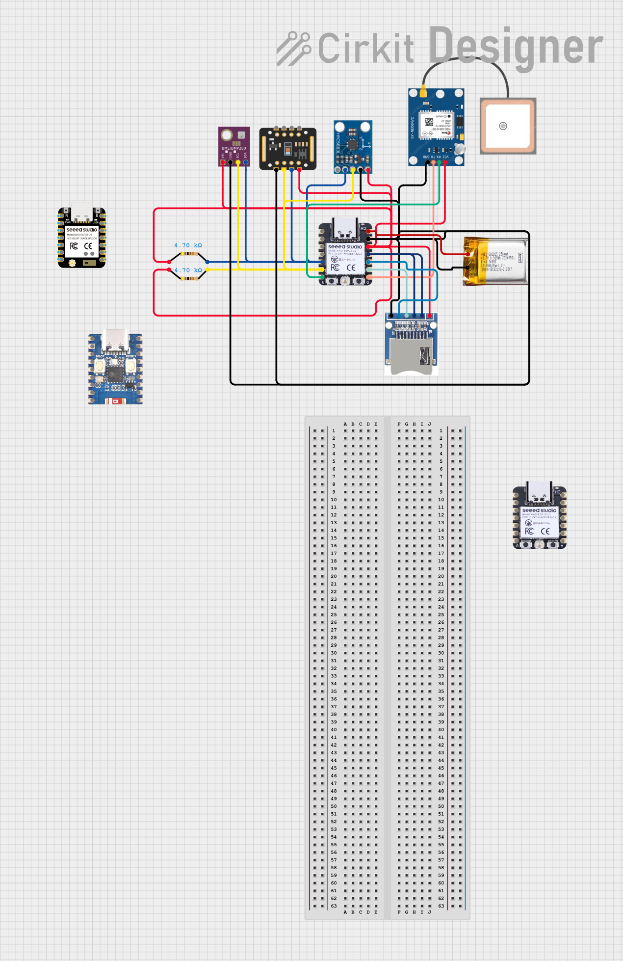 Open Project in Cirkit Designer
Explore Projects Built with OBD2 PORT
Open Project in Cirkit DesignerOpen Project in Cirkit DesignerOpen Project in Cirkit DesignerOpen Project in Cirkit DesignerTechnical Specifications
The OBD2 port follows a standardized pinout and communication protocol, ensuring compatibility across different vehicle makes and models. Below are the key technical details:
General Specifications
- Voltage Supply: 12V DC (typical for most vehicles).
- Communication Protocols Supported:
- SAE J1850 PWM (Pulse Width Modulation)
- SAE J1850 VPW (Variable Pulse Width)
- ISO 9141-2
- ISO 14230-4 (KWP2000)
- ISO 15765-4 (CAN bus)
- Connector Type: 16-pin D-shaped female connector.
- Data Rate: Varies by protocol (e.g., CAN bus supports up to 1 Mbps).
Pin Configuration and Descriptions
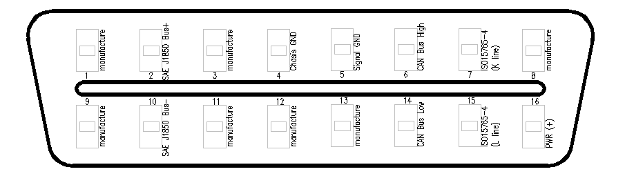
The OBD2 port has a 16-pin layout. Below is the pinout and description:
| Pin Number | Signal Name | Description |
|---|---|---|
| 1 | Vendor Option | Manufacturer-specific use (optional). |
| 2 | J1850 Bus+ | SAE J1850 PWM/VPW positive signal. |
| 3 | Vendor Option | Manufacturer-specific use (optional). |
| 4 | Chassis Ground | Ground connection for the vehicle chassis. |
| 5 | Signal Ground | Ground connection for signal reference. |
| 6 | CAN High (ISO 15765-4) | High line of the CAN bus. |
| 7 | K-Line (ISO 9141-2) | Communication line for ISO 9141-2 and ISO 14230-4 protocols. |
| 8 | Vendor Option | Manufacturer-specific use (optional). |
| 9 | Vendor Option | Manufacturer-specific use (optional). |
| 10 | J1850 Bus- | SAE J1850 PWM/VPW negative signal. |
| 11 | Vendor Option | Manufacturer-specific use (optional). |
| 12 | Vendor Option | Manufacturer-specific use (optional). |
| 13 | Vendor Option | Manufacturer-specific use (optional). |
| 14 | CAN Low (ISO 15765-4) | Low line of the CAN bus. |
| 15 | L-Line (ISO 9141-2) | Optional line for older ISO 9141-2 and ISO 14230-4 protocols. |
| 16 | Battery Power | Direct connection to the vehicle's battery (12V). |
Usage Instructions
How to Use the OBD2 Port in a Circuit
- Locate the OBD2 Port: The OBD2 port is typically located under the dashboard, near the driver's seat. Refer to the vehicle's manual for the exact location.
- Connect a Diagnostic Tool: Plug a compatible OBD2 scanner or diagnostic tool into the port. Ensure the tool supports the communication protocol used by the vehicle.
- Power On the Vehicle: Turn the ignition key to the "ON" position (engine off or running, depending on the diagnostic tool's requirements).
- Access Data: Use the diagnostic tool to read error codes, monitor live data, or perform specific tests. Follow the tool's instructions for navigation and operation.
- Disconnect Safely: Once diagnostics are complete, turn off the vehicle and unplug the tool from the OBD2 port.
Important Considerations and Best Practices
- Protocol Compatibility: Ensure the diagnostic tool supports the communication protocol used by the vehicle (e.g., CAN, ISO 9141-2).
- Avoid Overloading: Do not connect devices that draw excessive current from the OBD2 port, as it may damage the vehicle's electrical system.
- Secure Connections: Ensure the diagnostic tool is firmly connected to the port to avoid intermittent communication issues.
- Use Reliable Tools: Invest in high-quality OBD2 scanners or adapters to ensure accurate diagnostics and avoid potential damage to the vehicle.
Example: Using an OBD2 Adapter with Arduino UNO
An OBD2 adapter can be connected to an Arduino UNO for custom vehicle diagnostics. Below is an example code snippet for reading data from the OBD2 port using a CAN bus shield:
#include <SPI.h>
#include <mcp_can.h>

// Define the CAN bus shield's CS pin
#define CAN_CS_PIN 10

// Initialize the CAN bus object
MCP_CAN CAN(CAN_CS_PIN);

void setup() {
  Serial.begin(9600); // Initialize serial communication for debugging
  while (!Serial);

  // Initialize the CAN bus at 500 kbps (standard for most vehicles)
  if (CAN.begin(MCP_ANY, 500000, MCP_8MHZ) == CAN_OK) {
    Serial.println("CAN bus initialized successfully!");
  } else {
    Serial.println("Error initializing CAN bus.");
    while (1);
  }

  CAN.setMode(MCP_NORMAL); // Set CAN bus to normal mode
  Serial.println("CAN bus set to normal mode.");
}

void loop() {
  unsigned char len = 0;
  unsigned char buf[8];

  // Check for incoming CAN messages
  if (CAN.checkReceive() == CAN_MSGAVAIL) {
    CAN.readMsgBuf(&len, buf); // Read the message buffer

    Serial.print("Received CAN message: ");
    for (int i = 0; i < len; i++) {
      Serial.print(buf[i], HEX); // Print each byte in hexadecimal format
      Serial.print(" ");
    }
    Serial.println();
  }
}
Note: This example assumes the use of an MCP2515-based CAN bus shield. Ensure the shield is properly connected to the Arduino UNO and the OBD2 port.
Troubleshooting and FAQs
Common Issues
No Communication with the Vehicle:
- Cause: Incorrect protocol selection or incompatible diagnostic tool.
- Solution: Verify the vehicle's communication protocol and ensure the tool supports it.
Error Codes Not Clearing:
- Cause: Persistent fault in the vehicle system.
- Solution: Address the underlying issue before attempting to clear the codes.
Intermittent Connection:
- Cause: Loose or faulty OBD2 connector.
- Solution: Ensure the connector is securely plugged in and inspect for physical damage.
Diagnostic Tool Not Powering On:
- Cause: No power supply from the OBD2 port.
- Solution: Check the vehicle's fuse for the OBD2 port and replace if necessary.
FAQs
Q: Can I use the OBD2 port while driving?
A: Yes, but ensure the connected device is secure and does not interfere with driving.Q: Is the OBD2 port the same in all vehicles?
A: The physical connector and pinout are standardized, but supported protocols may vary.Q: Can I damage my vehicle by using the OBD2 port?
A: Using a high-quality, compatible diagnostic tool minimizes the risk of damage. Avoid connecting devices that draw excessive current.Q: What data can I access through the OBD2 port?
A: You can access engine parameters, error codes, emissions data, and more, depending on the vehicle and tool used.