Cirkit Designer Logo
Cirkit Designer
Your all-in-one circuit design IDE
Home / 
Component Documentation

How to Use Groove EMG Sensor: Examples, Pinouts, and Specs

Image of Groove EMG Sensor
Cirkit Designer LogoDesign with Groove EMG Sensor in Cirkit Designer

Introduction

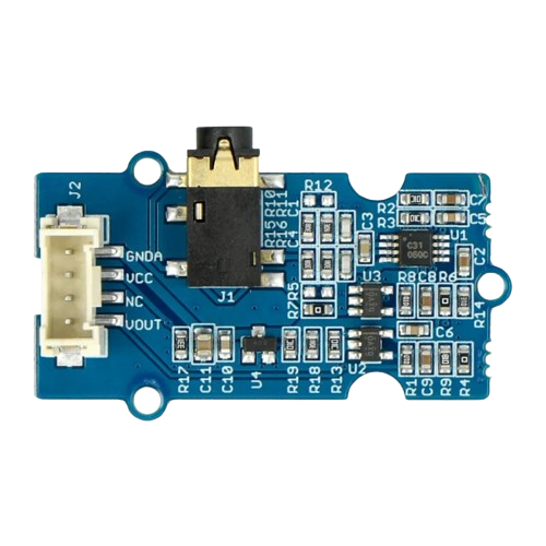
The Groove EMG Sensor is a specialized electronic component designed to detect the electrical activity generated by skeletal muscles. By measuring the electromyographic (EMG) signals, this sensor enables the monitoring of muscle contractions and movements. It is widely used in applications such as prosthetics, robotics, medical diagnostics, and human-computer interaction systems.

Common use cases include:

  • Monitoring muscle activity for rehabilitation or fitness tracking
  • Controlling robotic systems or prosthetic devices
  • Gesture recognition for gaming or virtual reality
  • Research in biomechanics and neuromuscular studies

Explore Projects Built with Groove EMG Sensor

Use Cirkit Designer to design, explore, and prototype these projects online. Some projects support real-time simulation. Click "Open Project" to start designing instantly!
Arduino UNO EMG Sensor-Controlled LCD Display with Piezo Buzzer
Image of MedInnov8 Posture Correcting Device v1: A project utilizing Groove EMG Sensor in a practical application
This circuit uses an Arduino UNO to read signals from a Grove EMG sensor and display the data on an LCD screen. It also includes a piezo buzzer for audio feedback and is powered by a 9V battery through a rocker switch and power jack.
Cirkit Designer LogoOpen Project in Cirkit Designer
Arduino-Powered EMG Sensor-Controlled Dual Servo System
Image of ARDUINO LIKHA EXOSKELETON: A project utilizing Groove EMG Sensor in a practical application
This circuit uses an Arduino UNO to control two servos based on input from an EMG sensor. The EMG sensor is powered by two 9V batteries and sends its signal to the Arduino, which then drives the servos connected to its digital pins.
Cirkit Designer LogoOpen Project in Cirkit Designer
Arduino-Controlled Servo with EMG Sensor Activation
Image of ARDUINO LIKHA EXOSKELETON: A project utilizing Groove EMG Sensor in a practical application
This circuit is designed to control a servo motor based on the signal from an EMG sensor, with the Arduino UNO as the central processing unit. The EMG sensor detects muscle activity, and when the signal exceeds a certain threshold, the servo motor is activated to move to a specific position. The pushbutton is connected to the Arduino to ground, likely for a reset or mode selection function, and the two 9V batteries power the EMG sensor and possibly the Arduino and servo.
Cirkit Designer LogoOpen Project in Cirkit Designer
Arduino UNO EMG Sensor and MPU-6050 Controlled Servo with LCD Display
Image of DuyBeni devre şeması v1: A project utilizing Groove EMG Sensor in a practical application
This circuit uses an Arduino UNO to process signals from an EMG sensor and an MPU-6050 accelerometer/gyroscope. The Arduino controls a servo motor based on the EMG sensor readings and displays the threshold value on an LCD. The MPU-6050 provides additional motion data via I2C communication.
Cirkit Designer LogoOpen Project in Cirkit Designer

Explore Projects Built with Groove EMG Sensor

Use Cirkit Designer to design, explore, and prototype these projects online. Some projects support real-time simulation. Click "Open Project" to start designing instantly!
Image of MedInnov8 Posture Correcting Device v1: A project utilizing Groove EMG Sensor in a practical application
Arduino UNO EMG Sensor-Controlled LCD Display with Piezo Buzzer
This circuit uses an Arduino UNO to read signals from a Grove EMG sensor and display the data on an LCD screen. It also includes a piezo buzzer for audio feedback and is powered by a 9V battery through a rocker switch and power jack.
Cirkit Designer LogoOpen Project in Cirkit Designer
Image of ARDUINO LIKHA EXOSKELETON: A project utilizing Groove EMG Sensor in a practical application
Arduino-Powered EMG Sensor-Controlled Dual Servo System
This circuit uses an Arduino UNO to control two servos based on input from an EMG sensor. The EMG sensor is powered by two 9V batteries and sends its signal to the Arduino, which then drives the servos connected to its digital pins.
Cirkit Designer LogoOpen Project in Cirkit Designer
Image of ARDUINO LIKHA EXOSKELETON: A project utilizing Groove EMG Sensor in a practical application
Arduino-Controlled Servo with EMG Sensor Activation
This circuit is designed to control a servo motor based on the signal from an EMG sensor, with the Arduino UNO as the central processing unit. The EMG sensor detects muscle activity, and when the signal exceeds a certain threshold, the servo motor is activated to move to a specific position. The pushbutton is connected to the Arduino to ground, likely for a reset or mode selection function, and the two 9V batteries power the EMG sensor and possibly the Arduino and servo.
Cirkit Designer LogoOpen Project in Cirkit Designer
Image of DuyBeni devre şeması v1: A project utilizing Groove EMG Sensor in a practical application
Arduino UNO EMG Sensor and MPU-6050 Controlled Servo with LCD Display
This circuit uses an Arduino UNO to process signals from an EMG sensor and an MPU-6050 accelerometer/gyroscope. The Arduino controls a servo motor based on the EMG sensor readings and displays the threshold value on an LCD. The MPU-6050 provides additional motion data via I2C communication.
Cirkit Designer LogoOpen Project in Cirkit Designer

Technical Specifications

The Groove EMG Sensor is designed for ease of use and compatibility with microcontrollers like Arduino. Below are its key technical details:

Parameter Value
Operating Voltage 3.3V to 5V
Operating Current < 10mA
Output Signal Range 0.3V to 1.5V (depending on muscle activity)
Gain Adjustable (default: 1000x)
Interface Type Analog
Dimensions 40mm x 20mm x 10mm

Pin Configuration and Descriptions

The Groove EMG Sensor has a 4-pin interface for easy connection. The pinout is as follows:

Pin Name Description
1 VCC Power supply pin (3.3V to 5V)
2 GND Ground connection
3 SIG Analog output signal representing muscle activity
4 NC Not connected (reserved for future use)

Usage Instructions

Connecting the Groove EMG Sensor

  1. Power Supply: Connect the VCC pin to a 3.3V or 5V power source and the GND pin to the ground of your circuit.
  2. Signal Output: Connect the SIG pin to an analog input pin on your microcontroller (e.g., Arduino).
  3. Electrode Placement: Attach the included electrodes to the muscle area you want to monitor. Ensure proper skin contact for accurate readings.
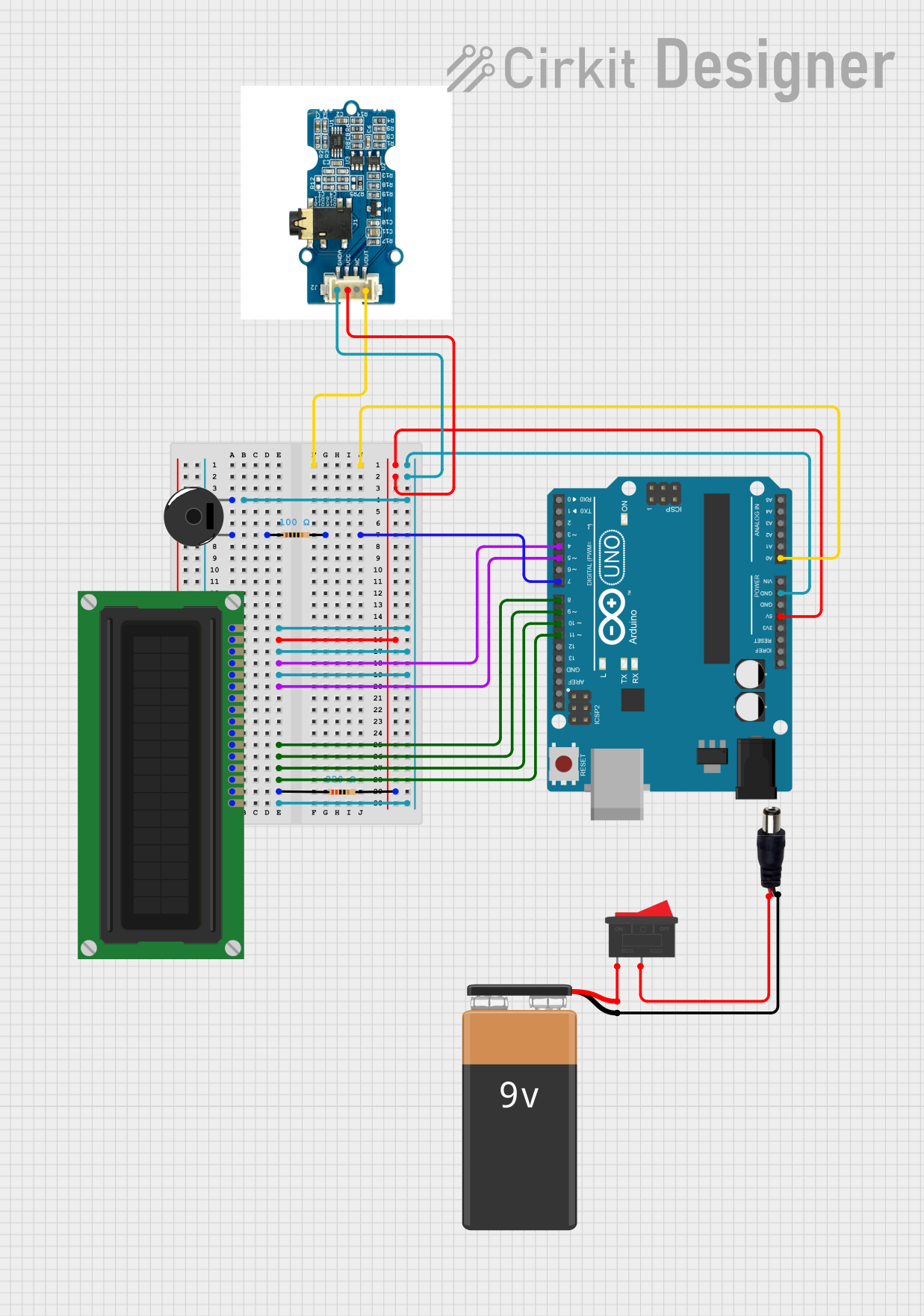
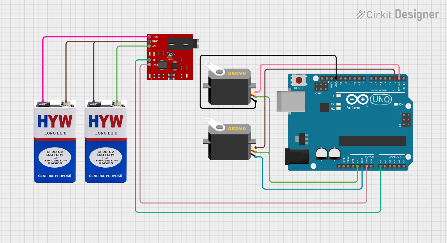
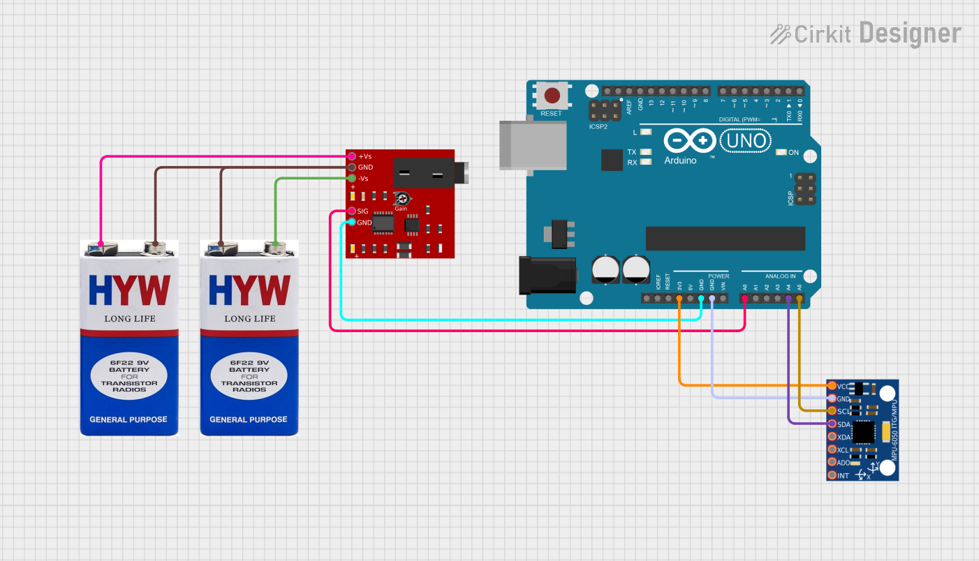
Example Circuit

Below is an example of how to connect the Groove EMG Sensor to an Arduino UNO:

  • VCC → 5V pin on Arduino
  • GND → GND pin on Arduino
  • SIG → A0 (analog input pin) on Arduino

Sample Arduino Code

The following code reads the EMG signal and outputs the values to the Serial Monitor:

// Groove EMG Sensor Example Code
// Connect SIG to A0, VCC to 5V, and GND to GND on Arduino UNO

const int emgPin = A0; // Analog pin connected to SIG
int emgValue = 0;      // Variable to store the EMG signal value

void setup() {
  Serial.begin(9600); // Initialize serial communication at 9600 baud
  pinMode(emgPin, INPUT); // Set the EMG pin as input
}

void loop() {
  emgValue = analogRead(emgPin); // Read the analog value from the sensor
  Serial.print("EMG Signal: ");  // Print label for clarity
  Serial.println(emgValue);     // Print the EMG signal value
  delay(100);                   // Delay for stability (adjust as needed)
}

Best Practices

  • Ensure the skin is clean and dry before attaching electrodes to improve signal quality.
  • Avoid placing electrodes near joints or bony areas for better readings.
  • Use shielded cables to minimize noise interference in the signal.
  • Calibrate the sensor gain if necessary to match your application requirements.

Troubleshooting and FAQs

Common Issues and Solutions

  1. No Signal Detected:

    • Ensure the electrodes are properly attached to the skin.
    • Verify that the sensor is powered correctly (check VCC and GND connections).
    • Check the analog input pin connection to the microcontroller.
  2. Noisy or Unstable Readings:

    • Ensure good skin contact and clean the skin before attaching electrodes.
    • Use shorter or shielded cables to reduce electrical noise.
    • Place the sensor away from high-frequency noise sources (e.g., motors).
  3. Low Signal Amplitude:

    • Adjust the gain setting on the sensor if possible.
    • Reposition the electrodes closer to the muscle of interest.

FAQs

Q: Can the Groove EMG Sensor be used with a 3.3V microcontroller?
A: Yes, the sensor operates within a voltage range of 3.3V to 5V, making it compatible with 3.3V systems like the ESP32.

Q: How do I clean the electrodes?
A: Use a damp cloth with mild soap to clean reusable electrodes. For disposable electrodes, replace them after each use.

Q: Can this sensor measure heart activity (ECG)?
A: No, the Groove EMG Sensor is specifically designed for muscle activity detection and is not suitable for ECG applications.

Q: What is the maximum distance between the sensor and the electrodes?
A: For best results, keep the distance as short as possible (less than 1 meter) to minimize signal degradation.

By following this documentation, you can effectively integrate the Groove EMG Sensor into your projects and achieve reliable results.