How to Use Adafruit INA237 85V 10A 16-bit DC Current Voltage Power Monitor: Examples, Pinouts, and Specs
Introduction
The Adafruit INA237 is a high-precision power monitor designed to measure DC current, voltage, and power with exceptional accuracy. Featuring a 16-bit resolution, it can handle up to 85V and 10A, making it suitable for a wide range of applications. The INA237 communicates via the I2C protocol, allowing seamless integration with microcontrollers and development boards such as the Arduino UNO.
Explore Projects Built with Adafruit INA237 85V 10A 16-bit DC Current Voltage Power Monitor
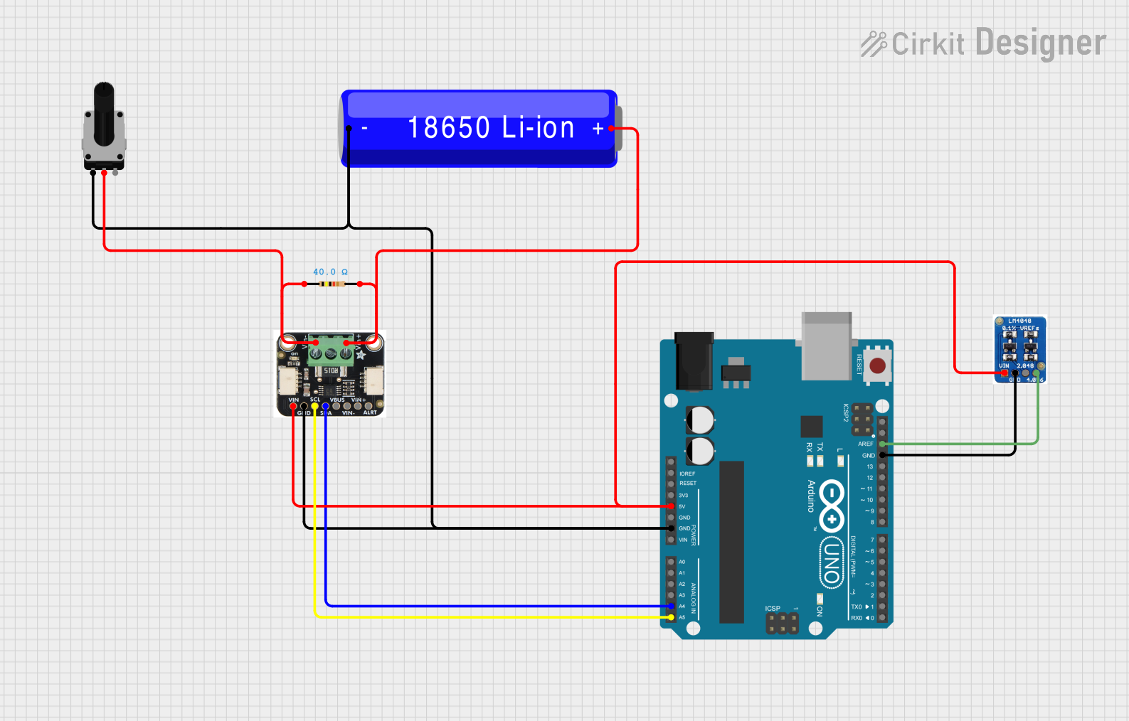
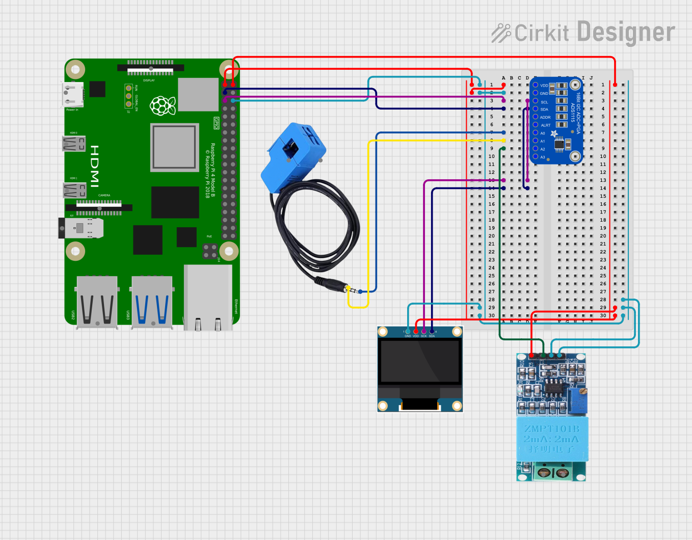
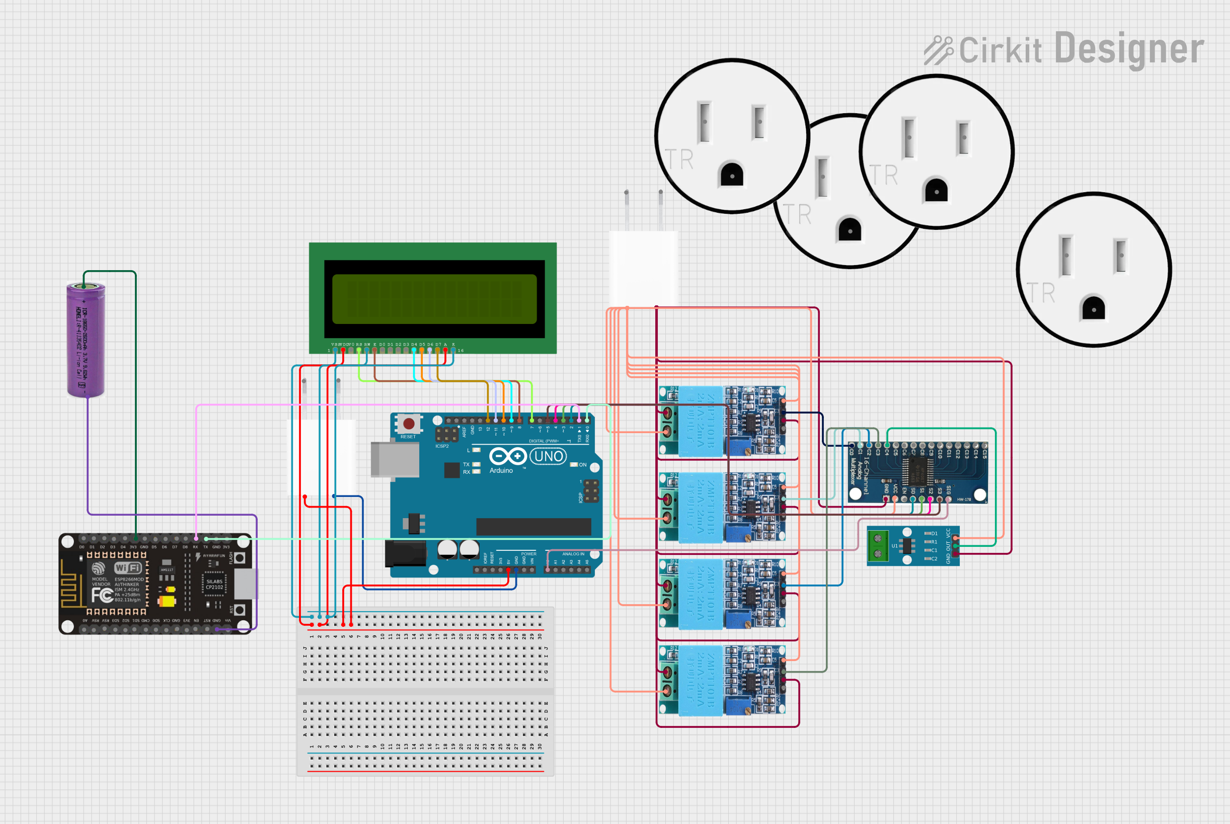

Explore Projects Built with Adafruit INA237 85V 10A 16-bit DC Current Voltage Power Monitor
Common Applications and Use Cases
- Battery management systems
- Solar power monitoring
- DC motor current sensing
- Power consumption analysis in embedded systems
- Industrial equipment monitoring
Technical Specifications
The Adafruit INA237 is a robust and versatile component. Below are its key technical details:
| Parameter | Value |
|---|---|
| Operating Voltage | 3.3V to 5V (logic level) |
| Measurable Voltage Range | 0V to 85V |
| Measurable Current Range | Up to 10A (with appropriate shunt resistor) |
| Resolution | 16-bit |
| Communication Protocol | I2C |
| Default I2C Address | 0x40 (configurable) |
| Operating Temperature | -40°C to +125°C |
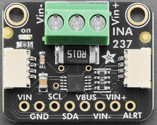
Pin Configuration and Descriptions
The Adafruit INA237 breakout board has the following pin layout:
| Pin Name | Description |
|---|---|
| VIN+ | Positive input for current sensing (connect to the high side of the load). |
| VIN- | Negative input for current sensing (connect to the low side of the load). |
| VBUS | Voltage sense input (connect to the voltage source being monitored). |
| GND | Ground reference for the circuit. |
| SCL | I2C clock line (connect to the microcontroller's SCL pin). |
| SDA | I2C data line (connect to the microcontroller's SDA pin). |
| ALERT | Configurable alert pin for overcurrent, overvoltage, or other conditions. |
| 3V3 | 3.3V power supply input (optional, for logic level shifting). |
| VIN | Main power supply input (3.3V to 5V). |
Usage Instructions
How to Use the Component in a Circuit
- Power the INA237: Connect the VIN pin to a 3.3V or 5V power source and GND to the ground.
- Connect the Load:
- Attach the VIN+ pin to the positive side of the load.
- Attach the VIN- pin to the negative side of the load.
- Voltage Sensing: Connect the VBUS pin to the voltage source you want to monitor.
- I2C Communication:
- Connect the SCL and SDA pins to the corresponding I2C pins on your microcontroller.
- Use pull-up resistors (typically 4.7kΩ) on the SCL and SDA lines if not already present.
- Optional Alert Pin: Use the ALERT pin to trigger an interrupt or signal when a specific condition is met (e.g., overcurrent).
Important Considerations and Best Practices
- Shunt Resistor Selection: The INA237 requires an external shunt resistor to measure current. Choose a resistor with a low resistance value and high power rating to minimize power loss and ensure accurate measurements.
- I2C Address Configuration: The default I2C address is 0x40. If multiple INA237 devices are used on the same I2C bus, configure their addresses using the onboard solder jumpers.
- Voltage and Current Limits: Ensure the monitored voltage and current do not exceed the component's maximum ratings (85V and 10A, respectively).
- Bypass Capacitor: Place a bypass capacitor (e.g., 0.1µF) near the power pins to reduce noise.
Example Code for Arduino UNO
Below is an example of how to use the Adafruit INA237 with an Arduino UNO to measure voltage, current, and power:
#include <Wire.h>
#include <Adafruit_INA237.h>

// Create an INA237 object
Adafruit_INA237 ina237;

void setup() {
  Serial.begin(115200);
  while (!Serial) {
    delay(10); // Wait for Serial Monitor to open
  }

  // Initialize I2C communication
  if (!ina237.begin()) {
    Serial.println("Failed to find INA237 chip!");
    while (1) {
      delay(10); // Halt if initialization fails
    }
  }
  Serial.println("INA237 initialized successfully!");

  // Configure the INA237
  ina237.setShuntResistorValue(0.01); // Set shunt resistor value in ohms
  ina237.setAveragingMode(INA237_AVERAGE_16); // Set averaging mode
  ina237.setBusVoltageRange(INA237_BUS_VOLTAGE_RANGE_85V); // Set voltage range
}

void loop() {
  // Read voltage, current, and power
  float busVoltage = ina237.readBusVoltage(); // Voltage in volts
  float current = ina237.readCurrent();       // Current in amps
  float power = ina237.readPower();           // Power in watts

  // Print the measurements to the Serial Monitor
  Serial.print("Bus Voltage: ");
  Serial.print(busVoltage);
  Serial.println(" V");

  Serial.print("Current: ");
  Serial.print(current);
  Serial.println(" A");

  Serial.print("Power: ");
  Serial.print(power);
  Serial.println(" W");

  delay(1000); // Wait 1 second before the next reading
}
Troubleshooting and FAQs
Common Issues and Solutions
INA237 Not Detected on I2C Bus:
- Ensure the SCL and SDA lines are correctly connected to the microcontroller.
- Verify that pull-up resistors are present on the I2C lines.
- Check the I2C address and ensure it matches the one configured on the INA237.
Incorrect Voltage or Current Readings:
- Double-check the shunt resistor value and ensure it is correctly set in the code.
- Verify that the connections to VIN+ and VIN- are secure and correct.
- Ensure the monitored voltage and current are within the component's specified range.
Alert Pin Not Functioning:
- Confirm that the ALERT pin is properly configured in the code.
- Check for any conditions that might prevent the alert from triggering (e.g., incorrect thresholds).
FAQs
Q: Can the INA237 measure negative currents?
A: No, the INA237 is designed for unidirectional current measurement. Ensure the current flows in the correct direction through the shunt resistor.
Q: What is the maximum sampling rate of the INA237?
A: The INA237 can achieve a maximum sampling rate of approximately 1.1kHz, depending on the averaging mode and configuration.
Q: Can I use the INA237 with a 3.3V microcontroller?
A: Yes, the INA237 is compatible with both 3.3V and 5V logic levels. Ensure the VIN pin is powered accordingly.
Q: How do I change the I2C address of the INA237?
A: The I2C address can be changed by modifying the solder jumpers on the breakout board. Refer to the Adafruit documentation for detailed instructions.