How to Use motor and wheels: Examples, Pinouts, and Specs
Introduction
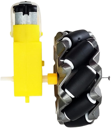
Motors and wheels are fundamental components in robotics, vehicles, and various automated systems. The motor converts electrical energy into mechanical energy, providing the necessary torque to drive the wheels, which in turn enable movement and support the structure they are attached to. These components are widely used in applications ranging from small DIY projects to large industrial machinery.
Explore Projects Built with motor and wheels

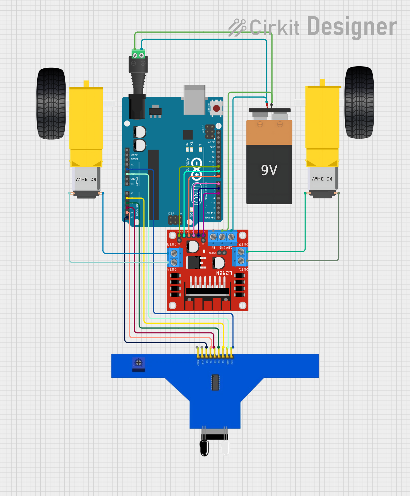
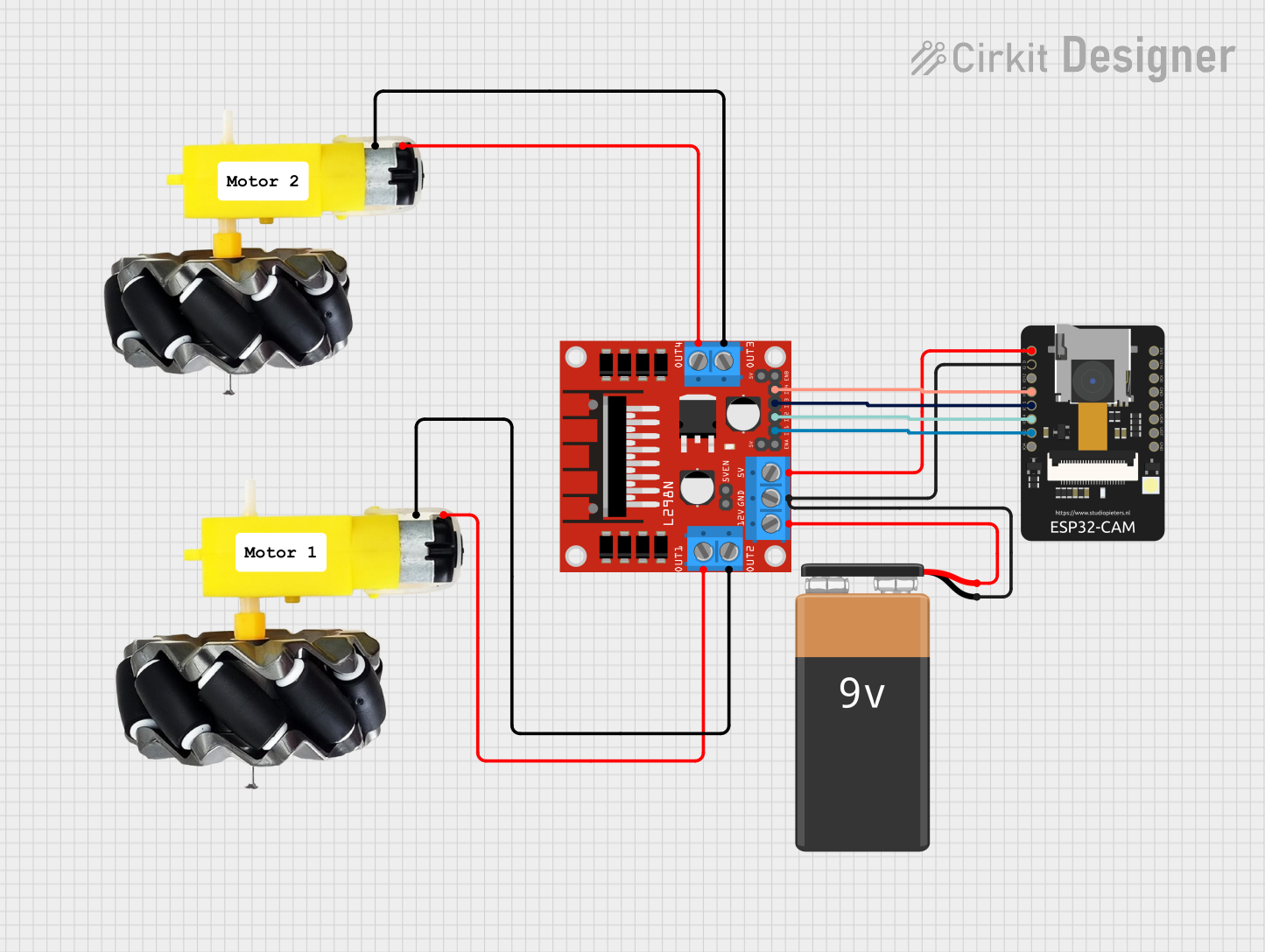
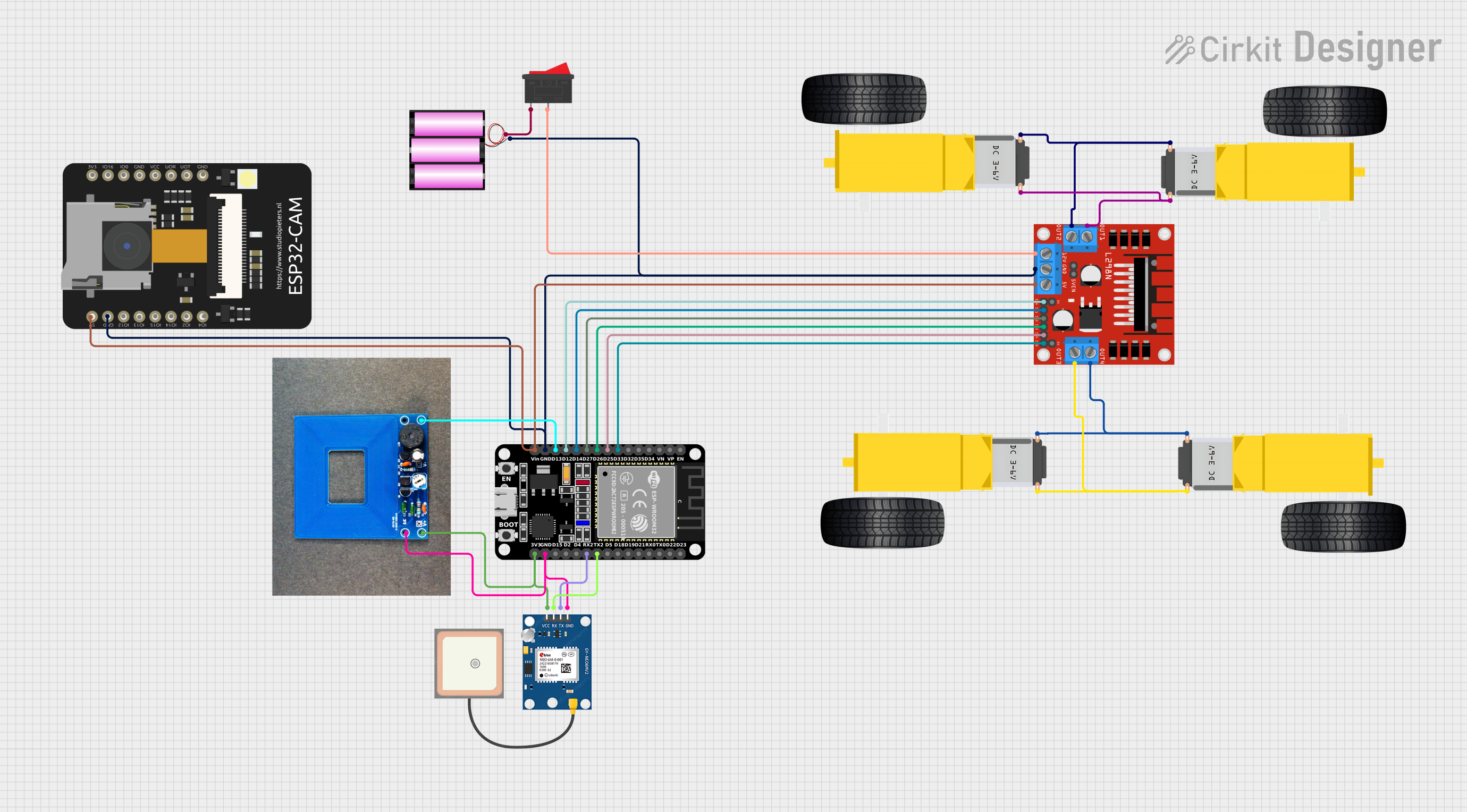
Explore Projects Built with motor and wheels
Technical Specifications
Motor Specifications
| Specification | Description |
|---|---|
| Voltage | 6V - 12V DC |
| Current | 250mA - 2A (no load - stall) |
| Power | Varies with usage, typically 1-10W |
| Speed | 100 - 10,000 RPM (depending on voltage and load) |
| Torque | 1 - 5 Nm (depending on model and load) |
| Shaft Diameter | 3mm - 6mm |
Wheel Specifications
| Specification | Description |
|---|---|
| Diameter | 65mm - 70mm (standard sizes) |
| Width | 25mm - 30mm |
| Material | Rubber, Plastic, or Polyurethane |
| Mounting Hub | Compatible with motor shaft diameter |
Pin Configuration for a Typical DC Motor
| Pin | Description |
|---|---|
| V+ | Connect to positive voltage supply |
| GND | Connect to ground |
Usage Instructions
Connecting the Motor to a Circuit
- Power Supply: Ensure that the power supply matches the voltage and current requirements of the motor.
- Motor Driver: Use a motor driver or H-bridge to control the direction and speed of the motor.
- PWM Control: For speed control, use Pulse Width Modulation (PWM) signals from a microcontroller like an Arduino UNO.
- Mounting Wheels: Attach the wheels to the motor shaft securely, ensuring they are aligned and rotate freely.
Best Practices
- Always use a motor driver to protect the microcontroller from high current draw.
- Incorporate flyback diodes to prevent back EMF damage when turning the motor off.
- Use proper gear ratios for the desired torque and speed.
- Avoid stalling the motor as it can lead to overheating and damage.
Example Code for Arduino UNO
#include <Arduino.h>

// Define motor control pins
const int motorPin1 = 3; // H-bridge leg 1 (pin 2, 1A)
const int motorPin2 = 4; // H-bridge leg 2 (pin 7, 2A)

void setup() {
  // Set motor control pins as outputs
  pinMode(motorPin1, OUTPUT);
  pinMode(motorPin2, OUTPUT);
}

void loop() {
  // Spin motor in one direction
  digitalWrite(motorPin1, HIGH);
  digitalWrite(motorPin2, LOW);
  delay(1000);

  // Stop motor
  digitalWrite(motorPin1, LOW);
  digitalWrite(motorPin2, LOW);
  delay(1000);

  // Spin motor in the opposite direction
  digitalWrite(motorPin1, LOW);
  digitalWrite(motorPin2, HIGH);
  delay(1000);

  // Stop motor
  digitalWrite(motorPin1, LOW);
  digitalWrite(motorPin2, LOW);
  delay(1000);
}
Troubleshooting and FAQs
Common Issues
- Motor not spinning: Check power supply, connections, and motor driver.
- Motor stalling: Reduce load or increase power supply.
- Uneven wheel movement: Ensure wheels are properly mounted and aligned.
FAQs
Q: Can I control the speed of the motor? A: Yes, by using PWM signals you can control the motor's speed.
Q: What should I do if the motor gets hot? A: Ensure the motor is not overloaded and has proper ventilation. If necessary, reduce usage or check for mechanical binding.
Q: How can I reverse the direction of the motor? A: Reverse the polarity of the motor's power supply, or use an H-bridge circuit to change the direction electronically.
Q: Can I use a different voltage than specified? A: Operating the motor outside its specified voltage range can damage the motor and void any warranty. Always adhere to the manufacturer's specifications.
For further assistance, consult the manufacturer's datasheet or contact technical support.