Cirkit Designer Logo
Cirkit Designer
Your all-in-one circuit design IDE
Home / 
Component Documentation

How to Use 12V Single Button Bistable Self-Locking Relay Module One-button Push to Start and Stop Self-locking Relay Module: Examples, Pinouts, and Specs

Image of 12V Single Button Bistable Self-Locking Relay Module One-button Push to Start and Stop Self-locking Relay Module
Cirkit Designer LogoDesign with 12V Single Button Bistable Self-Locking Relay Module One-button Push to Start and Stop Self-locking Relay Module in Cirkit Designer

Introduction

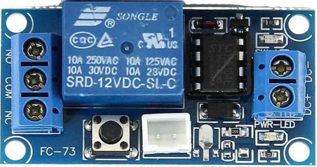
The 12V Single Button Bistable Self-Locking Relay Module by Hailege is a versatile electronic component designed for controlling high-voltage devices using a low-voltage signal. This module features a single push-button that toggles the relay state between ON and OFF, with a self-locking mechanism that retains the last state even after power loss. Its compact design and ease of use make it ideal for applications requiring simple on/off control.

Explore Projects Built with 12V Single Button Bistable Self-Locking Relay Module One-button Push to Start and Stop Self-locking Relay Module

Use Cirkit Designer to design, explore, and prototype these projects online. Some projects support real-time simulation. Click "Open Project" to start designing instantly!
Arduino Nano Controlled Relay System with Safety Interlocks
Image of HYD: A project utilizing 12V Single Button Bistable Self-Locking Relay Module One-button Push to Start and Stop Self-locking Relay Module in a practical application
This circuit includes an Arduino Nano microcontroller interfaced with multiple pushbuttons, limit switches, an emergency stop, a 2-channel relay module, and a 1-channel relay module. The Arduino controls the relay modules based on inputs from the pushbuttons and limit switches, which likely serve as user interfaces and position or safety sensors. The circuit is powered by a 5V power supply unit (PSU), which is connected to an AC supply, and the emergency stop is configured to potentially interrupt the circuit for safety purposes.
Cirkit Designer LogoOpen Project in Cirkit Designer
Battery-Powered Relay-Controlled Spark Ignition System
Image of spark plug electrical system: A project utilizing 12V Single Button Bistable Self-Locking Relay Module One-button Push to Start and Stop Self-locking Relay Module in a practical application
This circuit is designed to control a high-power device using a relay, which is activated by a pushbutton. The circuit includes a 12V battery for power, a fuse for protection, and a rocker switch to enable or disable the pushbutton control. When the pushbutton is pressed, it triggers the relay to connect the high-power device, which is protected by a copper coil.
Cirkit Designer LogoOpen Project in Cirkit Designer
Battery-Powered 4-Channel Relay Control with LED Indicators
Image of RELLAY BOARD TEST: A project utilizing 12V Single Button Bistable Self-Locking Relay Module One-button Push to Start and Stop Self-locking Relay Module in a practical application
This circuit consists of a 5V battery powering a 4-channel relay module, which controls four LEDs (red, yellow, green, and blue) through individual resistors. Each relay channel is activated by a corresponding SPST toggle switch, allowing manual control of the LEDs.
Cirkit Designer LogoOpen Project in Cirkit Designer
Battery-Powered LED Control with Pushbutton and Relay
Image of EXP.3 E: A project utilizing 12V Single Button Bistable Self-Locking Relay Module One-button Push to Start and Stop Self-locking Relay Module in a practical application
This circuit uses a pushbutton to control a 5V relay, which in turn powers a red LED. The MAHIR 1.mini module provides the necessary 3.7V power supply, and the relay switches the LED on and off based on the pushbutton input.
Cirkit Designer LogoOpen Project in Cirkit Designer

Explore Projects Built with 12V Single Button Bistable Self-Locking Relay Module One-button Push to Start and Stop Self-locking Relay Module

Use Cirkit Designer to design, explore, and prototype these projects online. Some projects support real-time simulation. Click "Open Project" to start designing instantly!
Image of HYD: A project utilizing 12V Single Button Bistable Self-Locking Relay Module One-button Push to Start and Stop Self-locking Relay Module in a practical application
Arduino Nano Controlled Relay System with Safety Interlocks
This circuit includes an Arduino Nano microcontroller interfaced with multiple pushbuttons, limit switches, an emergency stop, a 2-channel relay module, and a 1-channel relay module. The Arduino controls the relay modules based on inputs from the pushbuttons and limit switches, which likely serve as user interfaces and position or safety sensors. The circuit is powered by a 5V power supply unit (PSU), which is connected to an AC supply, and the emergency stop is configured to potentially interrupt the circuit for safety purposes.
Cirkit Designer LogoOpen Project in Cirkit Designer
Image of spark plug electrical system: A project utilizing 12V Single Button Bistable Self-Locking Relay Module One-button Push to Start and Stop Self-locking Relay Module in a practical application
Battery-Powered Relay-Controlled Spark Ignition System
This circuit is designed to control a high-power device using a relay, which is activated by a pushbutton. The circuit includes a 12V battery for power, a fuse for protection, and a rocker switch to enable or disable the pushbutton control. When the pushbutton is pressed, it triggers the relay to connect the high-power device, which is protected by a copper coil.
Cirkit Designer LogoOpen Project in Cirkit Designer
Image of RELLAY BOARD TEST: A project utilizing 12V Single Button Bistable Self-Locking Relay Module One-button Push to Start and Stop Self-locking Relay Module in a practical application
Battery-Powered 4-Channel Relay Control with LED Indicators
This circuit consists of a 5V battery powering a 4-channel relay module, which controls four LEDs (red, yellow, green, and blue) through individual resistors. Each relay channel is activated by a corresponding SPST toggle switch, allowing manual control of the LEDs.
Cirkit Designer LogoOpen Project in Cirkit Designer
Image of EXP.3 E: A project utilizing 12V Single Button Bistable Self-Locking Relay Module One-button Push to Start and Stop Self-locking Relay Module in a practical application
Battery-Powered LED Control with Pushbutton and Relay
This circuit uses a pushbutton to control a 5V relay, which in turn powers a red LED. The MAHIR 1.mini module provides the necessary 3.7V power supply, and the relay switches the LED on and off based on the pushbutton input.
Cirkit Designer LogoOpen Project in Cirkit Designer

Common Applications

  • Home automation systems (e.g., controlling lights, fans, or appliances)
  • Industrial equipment control
  • DIY electronics projects
  • Automotive systems for toggling devices like lights or pumps
  • Arduino and microcontroller-based projects

Technical Specifications

Below are the key technical details of the module:

Parameter Specification
Operating Voltage 12V DC
Trigger Method Single push-button
Relay Type Bistable (self-locking)
Maximum Load Voltage 250V AC / 30V DC
Maximum Load Current 10A
Module Dimensions 50mm x 26mm x 18mm
Power Consumption Low power consumption in idle state
Operating Temperature -40°C to 85°C
Indicator LEDs Power and relay state indicators

Pin Configuration and Descriptions

The module has a simple pinout for easy integration into circuits:

Pin Name Description
VCC Connect to 12V DC power supply
GND Connect to ground
NO Normally Open terminal of the relay
COM Common terminal of the relay
NC Normally Closed terminal of the relay

Usage Instructions

How to Use the Module in a Circuit

  1. Power the Module: Connect the VCC pin to a 12V DC power supply and the GND pin to ground.
  2. Connect the Load:
    • For devices that should be powered when the relay is ON, connect the load between the NO (Normally Open) and COM (Common) terminals.
    • For devices that should be powered when the relay is OFF, connect the load between the NC (Normally Closed) and COM terminals.
  3. Toggle the Relay: Press the onboard button to toggle the relay state between ON and OFF. The relay will maintain its state until the button is pressed again.
  4. Indicator LEDs: Observe the onboard LEDs:
    • Power LED indicates the module is powered.
    • Relay state LED indicates whether the relay is ON or OFF.

Important Considerations

  • Ensure the load connected to the relay does not exceed the maximum voltage (250V AC / 30V DC) or current (10A) ratings.
  • Use proper insulation and safety precautions when working with high-voltage devices.
  • If integrating with a microcontroller (e.g., Arduino), use an external transistor or optocoupler to trigger the relay safely.

Example: Connecting to an Arduino UNO

To control the relay module using an Arduino UNO, you can replace the onboard button with a digital signal from the Arduino. Below is an example code snippet:

// Define the pin connected to the relay module
const int relayPin = 7; // Connect Arduino pin 7 to the relay module's button input

// Variable to track the relay state
bool relayState = false;

void setup() {
  pinMode(relayPin, OUTPUT); // Set the relay pin as an output
  digitalWrite(relayPin, LOW); // Initialize the relay in the OFF state
}

void loop() {
  // Simulate a button press to toggle the relay state
  relayState = !relayState; // Toggle the relay state
  digitalWrite(relayPin, relayState ? HIGH : LOW); // Update the relay state
  
  delay(1000); // Wait for 1 second before toggling again
}

Note: The onboard button must be removed or bypassed when controlling the relay with an Arduino.

Troubleshooting and FAQs

Common Issues and Solutions

  1. Relay Does Not Toggle:

    • Ensure the module is powered with a stable 12V DC supply.
    • Check the onboard button or the control signal from the microcontroller.
    • Verify the load does not exceed the relay's maximum ratings.
  2. Relay Stays in One State:

    • Confirm the button or control signal is functioning correctly.
    • Inspect the relay module for physical damage or loose connections.
  3. Load Does Not Operate:

    • Check the wiring between the relay terminals and the load.
    • Ensure the load is functional and within the relay's voltage/current limits.

FAQs

Q: Can the module retain its state after a power outage?
A: Yes, the bistable relay design ensures the module retains its last state even after power is restored.

Q: Can I use this module with a 5V microcontroller?
A: Yes, but you will need a transistor or optocoupler to safely interface the 5V signal with the 12V relay module.

Q: Is the module suitable for AC loads?
A: Yes, the relay can handle AC loads up to 250V and 10A. Ensure proper insulation and safety precautions.

Q: Can I use this module for rapid switching?
A: No, the relay is not designed for high-frequency switching. Use a solid-state relay for such applications.