How to Use voltmeter: Examples, Pinouts, and Specs
Introduction
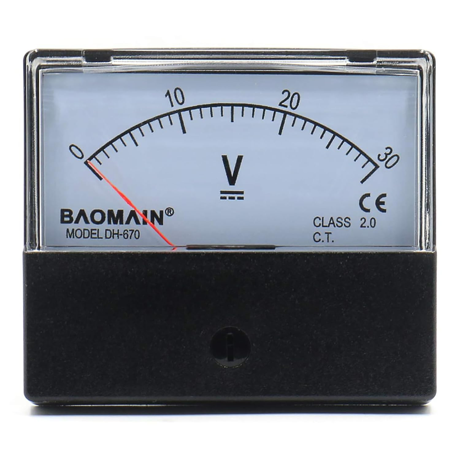
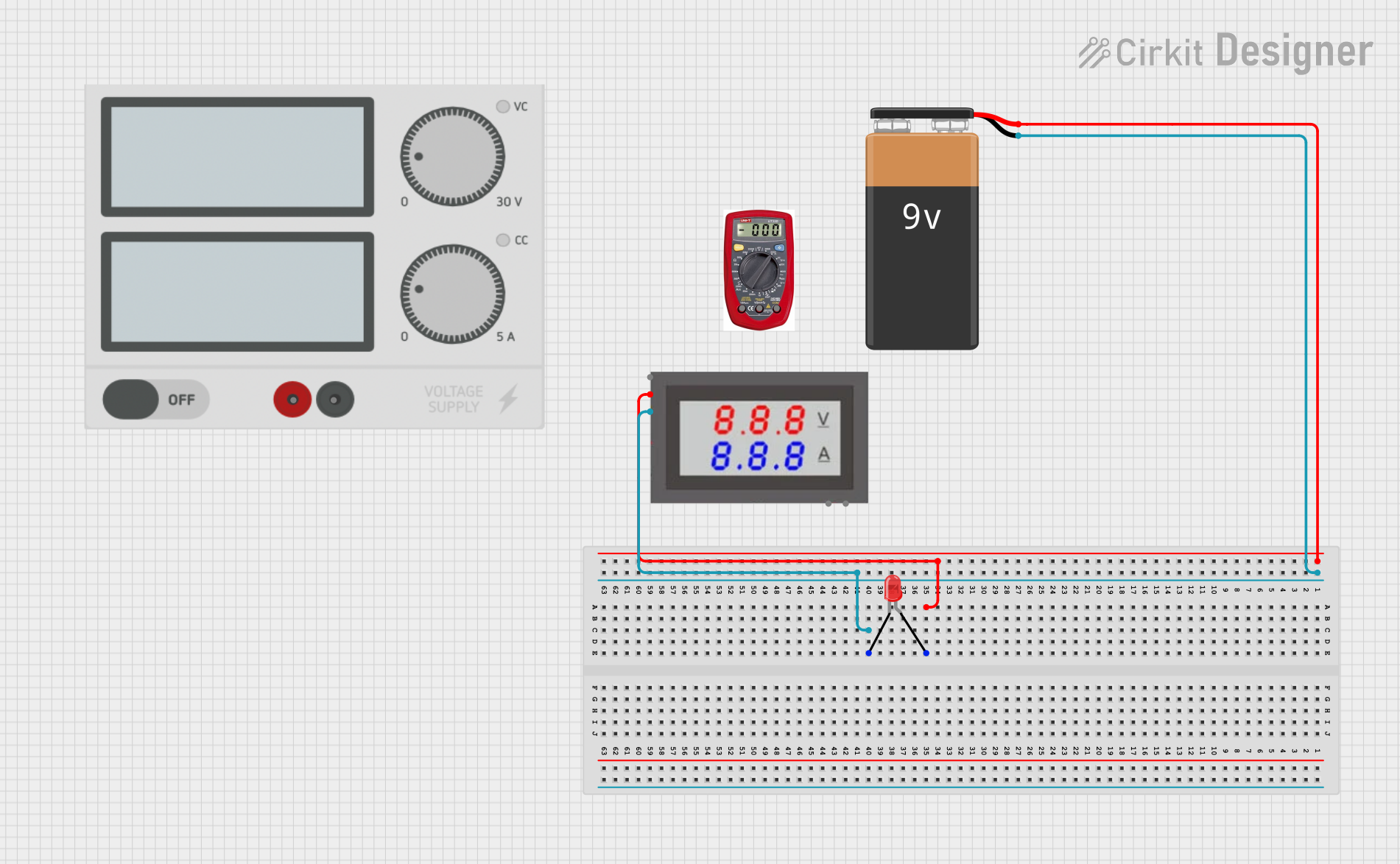
A voltmeter is an instrument used to measure the electrical potential difference, or voltage, between two points in an electric circuit. It is an essential tool for diagnosing, testing, and monitoring electrical systems. Voltmeters are available in both analog and digital forms, with digital voltmeters being more common due to their accuracy and ease of use.
Explore Projects Built with voltmeter
Explore Projects Built with voltmeter
Common Applications and Use Cases
- Measuring voltage in electrical circuits for troubleshooting and diagnostics.
- Monitoring battery voltage in automotive and renewable energy systems.
- Testing power supplies and electronic components.
- Educational purposes in electronics labs and training.
Technical Specifications
The specifications of a voltmeter can vary depending on the model and type. Below are general specifications for a typical digital voltmeter:
| Parameter | Specification |
|---|---|
| Voltage Range | 0V to 600V (DC and AC, depending on model) |
| Accuracy | ±0.5% to ±1% |
| Input Impedance | 1MΩ to 10MΩ |
| Display Type | LCD or LED |
| Power Supply | Battery-operated (e.g., 9V) or USB-powered |
| Resolution | 1mV to 1V (depending on range) |
| Sampling Rate | 2 to 5 readings per second |
Pin Configuration and Descriptions
For digital voltmeters with external connections, the pin configuration is typically as follows:
| Pin | Label | Description |
|---|---|---|
| 1 | V+ | Positive voltage input terminal |
| 2 | V- | Negative voltage input terminal (ground) |
| 3 | COM | Common ground for power supply (if applicable) |
Usage Instructions
How to Use the Voltmeter in a Circuit
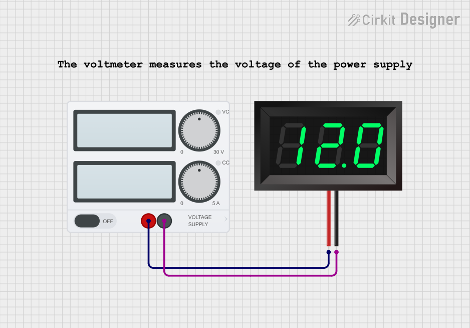
- Select the Voltage Range: Set the voltmeter to the appropriate voltage range (e.g., DC or AC) based on the circuit being measured. If unsure, start with the highest range to avoid damage.
- Connect the Probes:
- Attach the red probe to the positive terminal (V+).
- Attach the black probe to the negative terminal (V-) or ground.
- Take the Measurement: Read the voltage value displayed on the screen. For analog voltmeters, observe the needle position on the scale.
- Power Off: Turn off the voltmeter after use to conserve battery life.
Important Considerations and Best Practices
- Always ensure the voltmeter's range is higher than the expected voltage to prevent damage.
- Avoid measuring live circuits without proper safety precautions.
- For accurate readings, ensure the input impedance of the voltmeter is significantly higher than the circuit impedance.
- Regularly calibrate the voltmeter to maintain accuracy.
Example: Using a Voltmeter with an Arduino UNO
A voltmeter can be used to measure the output voltage of an Arduino UNO's analog pins. Below is an example of Arduino code to generate a voltage signal:
// Example: Generating a voltage signal on Arduino UNO
// Connect the voltmeter probes to GND and pin A0 to measure the output voltage.

const int analogPin = A0; // Define the analog pin
const int outputValue = 512; // Set output value (0-1023 for 0-5V range)

void setup() {
  pinMode(analogPin, OUTPUT); // Set the pin as output
}

void loop() {
  analogWrite(analogPin, outputValue);
  // Output a voltage proportional to outputValue
  // For example, 512 corresponds to ~2.5V (50% of 5V)
}
Troubleshooting and FAQs
Common Issues and Solutions
No Display or Incorrect Readings:
- Ensure the voltmeter is powered on and the battery is not depleted.
- Verify the probes are securely connected to the circuit.
- Check if the correct voltage range is selected.
Overload Indication:
- This occurs when the measured voltage exceeds the selected range. Switch to a higher range.
Fluctuating Readings:
- Ensure stable connections and avoid measuring in noisy environments.
- Use a voltmeter with higher input impedance for sensitive circuits.
Voltmeter Not Turning On:
- Replace the battery or check the power supply connection.
FAQs
Q: Can I use a voltmeter to measure current?
A: No, a voltmeter is designed to measure voltage. To measure current, use an ammeter or a multimeter with a current measurement mode.
Q: What happens if I connect the probes in reverse?
A: For digital voltmeters, the reading will show a negative value. For analog voltmeters, the needle may deflect in the opposite direction, potentially causing damage.
Q: How do I measure AC voltage?
A: Switch the voltmeter to the AC voltage mode and connect the probes to the circuit as usual. Ensure the range is appropriate for the expected voltage.
By following this documentation, users can effectively utilize a voltmeter for various applications while avoiding common pitfalls.