How to Use PAV3015: Examples, Pinouts, and Specs
Introduction
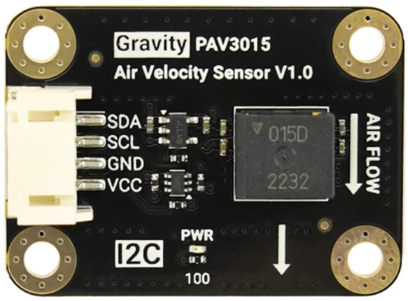
The PAV3015 is a high-performance operational amplifier (op-amp) manufactured by DF Robotics. It is specifically designed for precision signal processing applications, offering low noise, high gain, and a wide bandwidth. These features make the PAV3015 an ideal choice for applications requiring accurate and reliable signal amplification, such as audio systems, instrumentation, and control systems.
Explore Projects Built with PAV3015


Explore Projects Built with PAV3015
Common Applications and Use Cases
- Audio signal amplification in high-fidelity audio systems
- Precision instrumentation for scientific and industrial measurements
- Control systems requiring accurate signal processing
- Active filters, integrators, and differentiators in analog circuits
- Sensor signal conditioning in IoT and embedded systems
Technical Specifications
The PAV3015 is engineered to deliver exceptional performance in demanding applications. Below are its key technical specifications:
| Parameter | Value |
|---|---|
| Supply Voltage Range | ±2.5V to ±15V |
| Input Offset Voltage | 0.5 mV (typical) |
| Input Bias Current | 10 nA (typical) |
| Gain Bandwidth Product | 10 MHz |
| Slew Rate | 5 V/µs |
| Noise Density | 4 nV/√Hz at 1 kHz |
| Output Voltage Swing | ±13.5V (with ±15V supply) |
| Input Impedance | 10 MΩ |
| Operating Temperature | -40°C to +85°C |
| Package Type | 8-pin DIP or SOIC |
Pin Configuration and Descriptions
The PAV3015 is available in an 8-pin package. The pinout and descriptions are as follows:
| Pin Number | Pin Name | Description |
|---|---|---|
| 1 | Offset Null | Offset voltage adjustment (connect to potentiometer) |
| 2 | Inverting Input (-) | Inverting input terminal for the op-amp |
| 3 | Non-Inverting Input (+) | Non-inverting input terminal for the op-amp |
| 4 | V- (Negative Supply) | Negative power supply terminal |
| 5 | Offset Null | Offset voltage adjustment (connect to potentiometer) |
| 6 | Output | Output terminal of the op-amp |
| 7 | V+ (Positive Supply) | Positive power supply terminal |
| 8 | NC (No Connection) | Not connected internally |
Usage Instructions
The PAV3015 is straightforward to use in a variety of circuit designs. Below are the steps and best practices for integrating the PAV3015 into your project:
Basic Circuit Configuration
- Power Supply: Connect the V+ (pin 7) and V- (pin 4) pins to the positive and negative power supply rails, respectively. Ensure the supply voltage is within the specified range (±2.5V to ±15V).
- Input Connections: Connect the signal source to the inverting input (pin 2) or non-inverting input (pin 3), depending on the desired configuration (e.g., inverting or non-inverting amplifier).
- Output Connection: Connect the output (pin 6) to the load or the next stage of the circuit.
- Offset Adjustment: If precise offset voltage adjustment is required, connect a 10 kΩ potentiometer between the offset null pins (pins 1 and 5) and the wiper to V+.
Example: Non-Inverting Amplifier Circuit
Below is an example of a non-inverting amplifier circuit using the PAV3015:
        +V (e.g., +12V)
         |
         |
        [R1] 10 kΩ
         |
         |---------> Non-Inverting Input (+) (Pin 3)
         |                  |
         |                  |
        [R2] 100 kΩ         |
         |                  |
         |                  |
        GND                Output (Pin 6)
                           |
                           |
                          [Load]
                           |
                          GND
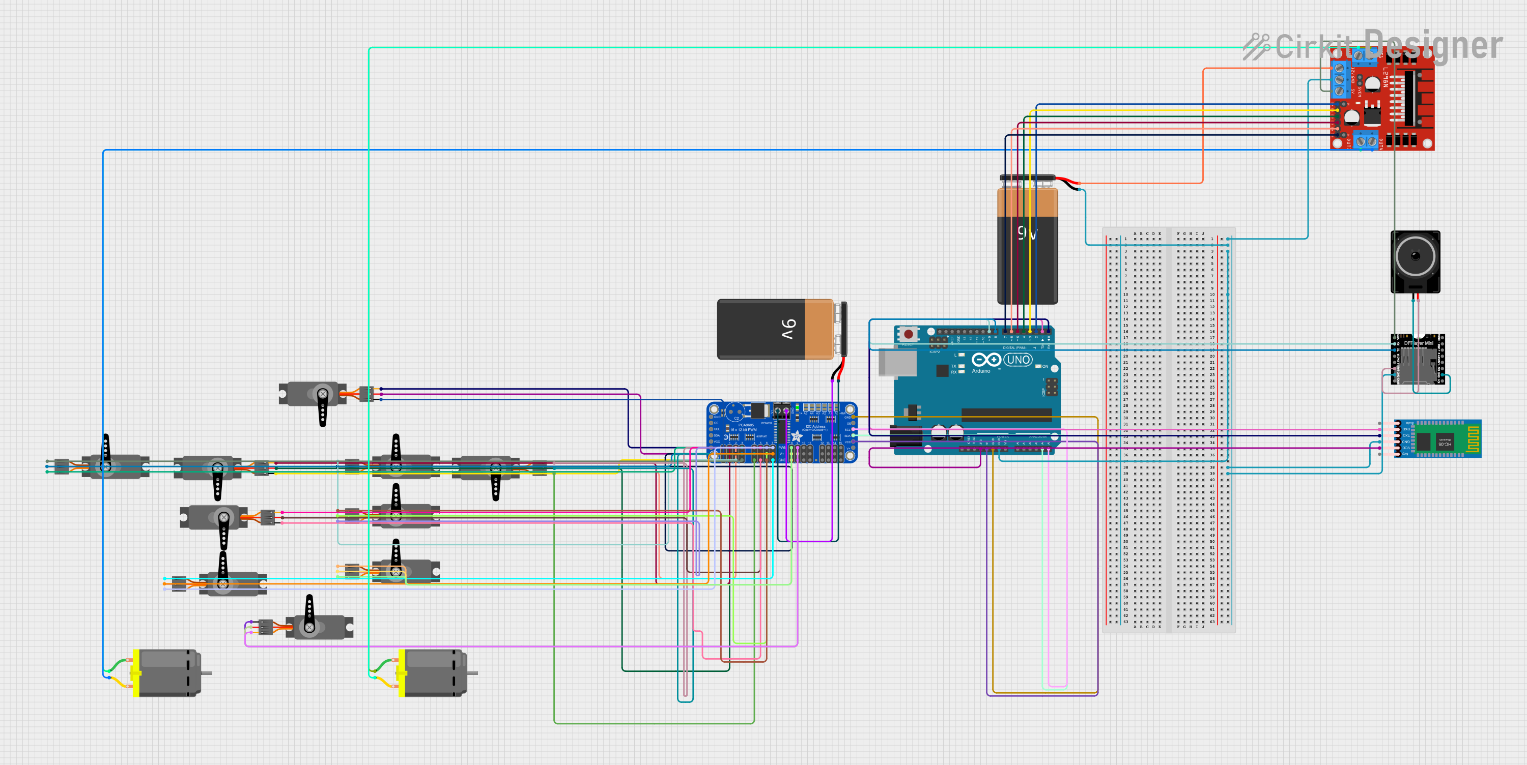
Arduino UNO Integration
The PAV3015 can be used with an Arduino UNO for sensor signal conditioning. Below is an example Arduino sketch for reading an amplified sensor signal:
// Example Arduino code for reading a signal amplified by the PAV3015
const int sensorPin = A0; // Analog pin connected to the PAV3015 output
int sensorValue = 0;      // Variable to store the sensor reading

void setup() {
  Serial.begin(9600); // Initialize serial communication at 9600 baud
}

void loop() {
  sensorValue = analogRead(sensorPin); // Read the amplified signal
  float voltage = sensorValue * (5.0 / 1023.0); // Convert to voltage
  Serial.print("Sensor Voltage: ");
  Serial.println(voltage); // Print the voltage to the Serial Monitor
  delay(500); // Wait for 500 ms before the next reading
}
Best Practices
- Use decoupling capacitors (e.g., 0.1 µF ceramic) close to the power supply pins to reduce noise.
- Avoid exceeding the maximum supply voltage to prevent damage to the component.
- Ensure proper grounding to minimize noise and interference.
- Use shielded cables for input signals in noisy environments.
Troubleshooting and FAQs
Common Issues and Solutions
No Output Signal:
- Verify the power supply connections and ensure the supply voltage is within the specified range.
- Check the input signal and ensure it is properly connected to the correct input pin.
Distorted Output Signal:
- Ensure the load connected to the output is within the op-amp's drive capability.
- Check for proper decoupling of the power supply to reduce noise.
High Offset Voltage:
- Use the offset null pins to adjust and minimize the offset voltage.
Excessive Noise:
- Ensure proper grounding and shielding of input signals.
- Use low-noise resistors and components in the circuit.
FAQs
Q: Can the PAV3015 be used for single-supply operation?
A: Yes, the PAV3015 can be configured for single-supply operation by connecting the V- pin to ground. However, ensure the input signal and output swing are within the allowable range for single-supply operation.
Q: What is the maximum load the PAV3015 can drive?
A: The PAV3015 can drive loads with a resistance as low as 2 kΩ. For lower resistance loads, consider using a buffer stage.
Q: How do I minimize noise in my circuit?
A: Use proper decoupling capacitors, shielded cables, and low-noise components. Additionally, keep the layout compact and avoid long traces for sensitive signals.
This concludes the documentation for the PAV3015 operational amplifier. For further assistance, refer to the DF Robotics datasheet or contact their technical support.