How to Use MAX31865: Examples, Pinouts, and Specs
Introduction
The MAX31865 is a precision digital temperature sensor interface designed specifically for RTD (Resistance Temperature Detector) sensors. It simplifies the process of interfacing RTDs with microcontrollers by providing a high-accuracy, digital output via SPI (Serial Peripheral Interface) communication. The MAX31865 supports both 2-wire, 3-wire, and 4-wire RTD configurations, making it versatile for a wide range of temperature measurement applications.
Explore Projects Built with MAX31865


Explore Projects Built with MAX31865
Common Applications and Use Cases
- Industrial temperature monitoring and control
- HVAC systems
- Laboratory-grade temperature measurement
- Process automation
- Embedded systems requiring precise temperature sensing
Technical Specifications
The MAX31865 is designed to work seamlessly with RTDs, such as the PT100 and PT1000, and offers the following key specifications:
Key Technical Details
- Supply Voltage (VDD): 3.0V to 3.6V
- Operating Temperature Range: -40°C to +125°C
- RTD Compatibility: PT100, PT1000 (2-wire, 3-wire, or 4-wire)
- Communication Interface: SPI (up to 5 MHz)
- Input Impedance: > 1 MΩ
- Fault Detection: Open-circuit, short-circuit, and over/under-voltage
- Reference Resistor: External, typically 400Ω for PT100 or 4kΩ for PT1000
- Package: 20-pin TQFN or 16-pin SOIC
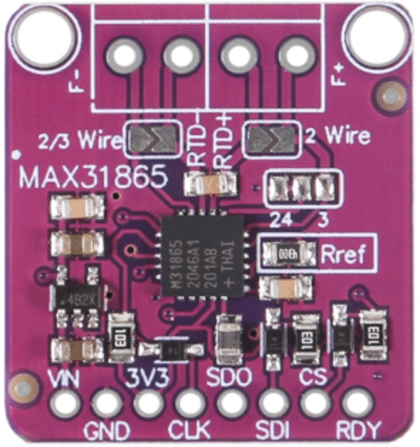
Pin Configuration and Descriptions
The MAX31865 has the following pinout:
16-Pin SOIC Package
| Pin Number | Pin Name | Description |
|---|---|---|
| 1 | VDD | Power supply input (3.0V to 3.6V). |
| 2 | GND | Ground connection. |
| 3 | SDI | SPI data input (MOSI). |
| 4 | SDO | SPI data output (MISO). |
| 5 | SCLK | SPI clock input. |
| 6 | CS | Chip select (active low). |
| 7 | RTDIN+ | Positive input for RTD sensor. |
| 8 | RTDIN- | Negative input for RTD sensor. |
| 9 | FORCE+ | Positive force connection for RTD excitation current. |
| 10 | FORCE- | Negative force connection for RTD excitation current. |
| 11 | REFIN+ | Positive input for reference resistor. |
| 12 | REFIN- | Negative input for reference resistor. |
| 13 | FAULT | Fault detection output (active low). |
| 14 | DRDY | Data ready output (active low). |
| 15 | N.C. | No connection. Leave unconnected. |
| 16 | N.C. | No connection. Leave unconnected. |
Usage Instructions
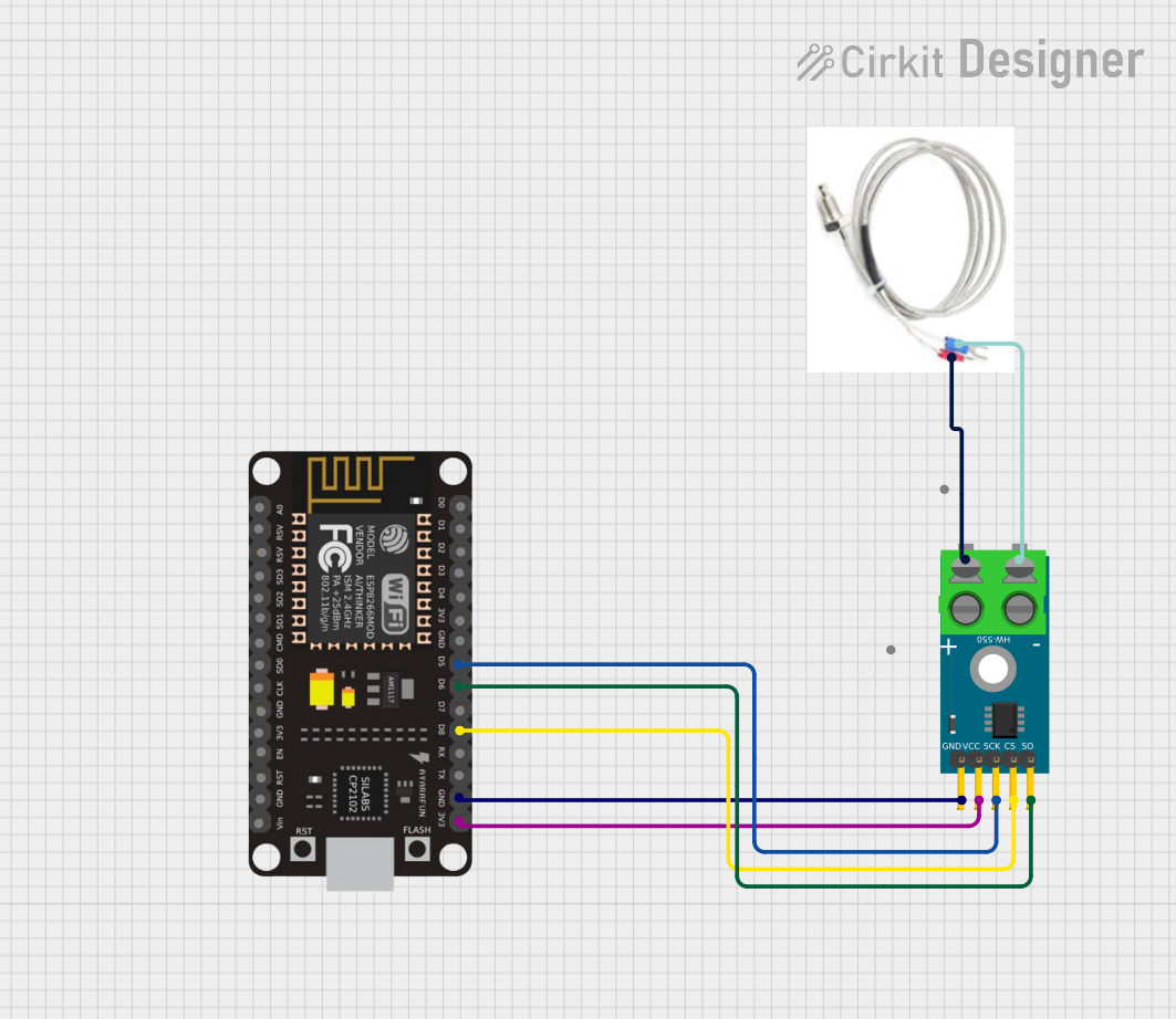
How to Use the MAX31865 in a Circuit
- Power Supply: Connect the VDD pin to a 3.3V power source and GND to ground.
- RTD Connection:
- For a 2-wire RTD, connect the RTD leads to RTDIN+ and RTDIN-.
- For a 3-wire RTD, connect the third lead to FORCE+.
- For a 4-wire RTD, connect the additional leads to FORCE+ and FORCE-.
- Reference Resistor: Connect a precision reference resistor (e.g., 400Ω for PT100) between REFIN+ and REFIN-.
- SPI Communication: Connect the SPI pins (SDI, SDO, SCLK, and CS) to the corresponding pins on your microcontroller.
- Fault Detection: Optionally, connect the FAULT pin to monitor error conditions.
Important Considerations and Best Practices
- Use a high-precision reference resistor to ensure accurate temperature measurements.
- Keep the RTD and reference resistor connections as short as possible to minimize noise.
- Use proper decoupling capacitors (e.g., 0.1µF) near the VDD pin to stabilize the power supply.
- Ensure the SPI clock frequency does not exceed 5 MHz.
- For 3-wire RTDs, ensure the third wire is of the same resistance as the other two to maintain accuracy.
Example Code for Arduino UNO
Below is an example of how to interface the MAX31865 with an Arduino UNO using the SPI library:
#include <SPI.h>

// Define MAX31865 pins
#define CS_PIN 10  // Chip select pin for MAX31865

void setup() {
  // Initialize serial communication for debugging
  Serial.begin(9600);

  // Initialize SPI communication
  SPI.begin();
  pinMode(CS_PIN, OUTPUT);
  digitalWrite(CS_PIN, HIGH); // Set CS pin high to deselect MAX31865

  // Configure MAX31865 (e.g., write to configuration register)
  configureMAX31865();
}

void loop() {
  // Read temperature data from MAX31865
  float temperature = readTemperature();
  Serial.print("Temperature: ");
  Serial.print(temperature);
  Serial.println(" °C");

  delay(1000); // Wait 1 second before the next reading
}

void configureMAX31865() {
  digitalWrite(CS_PIN, LOW); // Select MAX31865
  SPI.transfer(0x80);        // Write to configuration register
  SPI.transfer(0xC2);        // Enable Vbias, set 3-wire RTD mode
  digitalWrite(CS_PIN, HIGH); // Deselect MAX31865
}

float readTemperature() {
  uint16_t rtdData;

  // Read RTD resistance data
  digitalWrite(CS_PIN, LOW); // Select MAX31865
  SPI.transfer(0x01);        // Read RTD MSB
  rtdData = SPI.transfer(0x00) << 8; // Read MSB
  rtdData |= SPI.transfer(0x00);     // Read LSB
  digitalWrite(CS_PIN, HIGH); // Deselect MAX31865

  // Calculate temperature (example for PT100, adjust for PT1000)
  float resistance = (rtdData >> 1) * 400.0 / 32768.0; // Convert to resistance
  float temperature = (resistance - 100.0) / 0.385;    // Convert to temperature
  return temperature;
}
Troubleshooting and FAQs
Common Issues and Solutions
No Temperature Reading:
- Ensure the SPI connections (SDI, SDO, SCLK, CS) are correct.
- Verify the power supply voltage is within the specified range (3.0V to 3.6V).
- Check that the RTD and reference resistor are properly connected.
Inaccurate Temperature Measurements:
- Use a high-precision reference resistor with low temperature coefficient.
- Minimize noise by keeping connections short and using shielded cables if necessary.
- Verify the RTD type (e.g., PT100 or PT1000) matches the configuration.
Fault Pin is Active:
- Check for open or short circuits in the RTD connections.
- Ensure the reference resistor is not damaged or disconnected.
FAQs
Q: Can I use the MAX31865 with a 5V microcontroller?
A: Yes, but you will need a level shifter to interface the 3.3V SPI signals with the 5V microcontroller.
Q: What is the maximum cable length for the RTD?
A: The maximum cable length depends on the wire resistance and noise environment. For long cables, use a 3-wire or 4-wire RTD configuration to compensate for lead resistance.
Q: Can I use the MAX31865 with other RTD types?
A: The MAX31865 is optimized for PT100 and PT1000 RTDs. Other RTD types may require additional calibration or adjustments.