
How to Use RS485_SP491: Examples, Pinouts, and Specs
 Design with RS485_SP491 in Cirkit Designer
Introduction
The RS485_SP491, manufactured by Sipex, is a robust transceiver designed for balanced data transmission over long distances in noisy environments. It supports half-duplex communication, making it ideal for applications where bidirectional data exchange is required but only one device transmits at a time. The SP491 is widely used in industrial automation, control systems, building management systems, and other applications requiring reliable communication over twisted-pair cables.
Explore Projects Built with RS485_SP491
 Open Project in Cirkit Designer
 Open Project in Cirkit Designer
 Open Project in Cirkit Designer
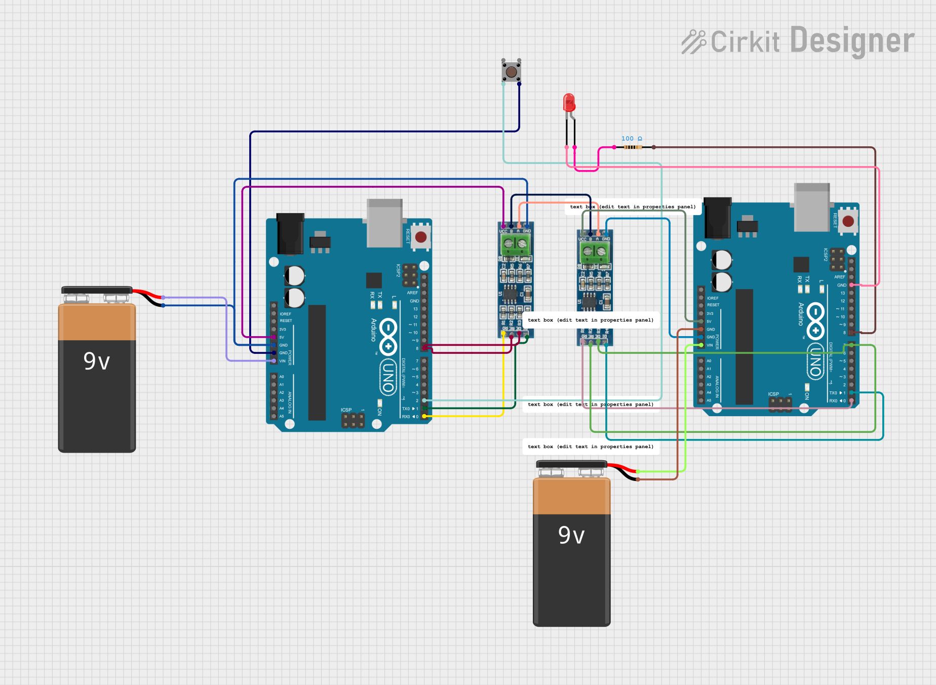 Open Project in Cirkit Designer
Explore Projects Built with RS485_SP491
Open Project in Cirkit DesignerOpen Project in Cirkit DesignerOpen Project in Cirkit DesignerOpen Project in Cirkit DesignerCommon Applications:
- Industrial automation and control systems
- Building management systems
- Remote data acquisition
- RS-485-based communication networks
- Motor control and monitoring systems
Technical Specifications
Key Technical Details:
- Manufacturer Part ID: SP491
- Communication Standard: RS-485
- Operating Voltage: 4.75V to 5.25V
- Data Rate: Up to 10 Mbps
- Driver Output Voltage: ±5V (minimum)
- Receiver Input Sensitivity: ±200 mV
- Operating Temperature Range: -40°C to +85°C
- Power Consumption: Low power consumption with a typical supply current of 500 µA
- ESD Protection: ±15 kV (Human Body Model)
- Package Type: 8-pin DIP or SOIC
Pin Configuration and Descriptions:
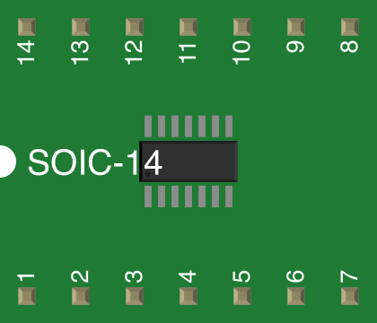
The SP491 is an 8-pin device. Below is the pinout and description:
| Pin Number | Pin Name | Description |
|---|---|---|
| 1 | RO | Receiver Output: Outputs the received data signal. |
| 2 | RE (Active Low) | Receiver Enable: Enables the receiver when low. Disables the receiver when high. |
| 3 | DE | Driver Enable: Enables the driver when high. Disables the driver when low. |
| 4 | DI | Driver Input: Accepts the data to be transmitted. |
| 5 | GND | Ground: Connect to the system ground. |
| 6 | A | Non-inverting Driver Output / Receiver Input. |
| 7 | B | Inverting Driver Output / Receiver Input. |
| 8 | VCC | Power Supply: Connect to a 5V power source. |
Usage Instructions
How to Use the RS485_SP491 in a Circuit:
- Power Supply: Connect the VCC pin to a regulated 5V power source and the GND pin to the system ground.
- Data Transmission:
- Connect the DI pin to the microcontroller or data source for transmitting data.
- Use the DE pin to enable the driver. Set DE high to enable transmission and low to disable it.
- Data Reception:
- Connect the RO pin to the microcontroller or data sink for receiving data.
- Use the RE pin to enable the receiver. Set RE low to enable reception and high to disable it.
- Differential Pair:
- Connect the A and B pins to the differential twisted-pair cable for RS-485 communication.
- Ensure proper termination resistors (typically 120Ω) are placed at both ends of the cable to minimize signal reflections.
- Half-Duplex Communication:
- Since the SP491 supports half-duplex communication, ensure that only one device transmits at a time while others are in receive mode.
Important Considerations:
- Termination Resistors: Always use termination resistors at both ends of the RS-485 bus to maintain signal integrity.
- Biasing Resistors: Use pull-up and pull-down resistors on the A and B lines to ensure a known idle state when no device is transmitting.
- ESD Protection: The SP491 includes built-in ESD protection, but additional external protection may be added for harsh environments.
- Cable Selection: Use twisted-pair cables with proper shielding for long-distance communication to reduce noise interference.
Example Code for Arduino UNO:
Below is an example of how to use the RS485_SP491 with an Arduino UNO for basic communication:
// RS485_SP491 Arduino Example
// This example demonstrates sending and receiving data using the SP491 transceiver.
// Connect the DI pin to Arduino TX, RO pin to Arduino RX, DE and RE to a digital pin.

#define DE_PIN 2  // Driver Enable pin connected to Arduino digital pin 2
#define RE_PIN 3  // Receiver Enable pin connected to Arduino digital pin 3

void setup() {
  Serial.begin(9600);  // Initialize serial communication at 9600 baud
  pinMode(DE_PIN, OUTPUT);  // Set DE pin as output
  pinMode(RE_PIN, OUTPUT);  // Set RE pin as output

  // Set the transceiver to receive mode initially
  digitalWrite(DE_PIN, LOW);  // Disable driver
  digitalWrite(RE_PIN, LOW);  // Enable receiver
}

void loop() {
  // Example: Sending data
  digitalWrite(DE_PIN, HIGH);  // Enable driver
  digitalWrite(RE_PIN, HIGH);  // Disable receiver
  Serial.println("Hello, RS485!");  // Send data
  delay(1000);  // Wait for 1 second

  // Example: Receiving data
  digitalWrite(DE_PIN, LOW);  // Disable driver
  digitalWrite(RE_PIN, LOW);  // Enable receiver
  if (Serial.available()) {
    String receivedData = Serial.readString();  // Read received data
    Serial.println("Received: " + receivedData);  // Print received data
  }
}
Troubleshooting and FAQs
Common Issues and Solutions:
No Communication Between Devices:
- Ensure the A and B lines are correctly connected between devices.
- Verify that the DE and RE pins are set correctly for transmission and reception.
- Check for proper termination resistors at both ends of the RS-485 bus.
Data Corruption or Noise:
- Use shielded twisted-pair cables to reduce noise interference.
- Verify that the cable length does not exceed the RS-485 standard limit (typically 1200 meters).
- Ensure proper grounding of the system.
Overheating of the SP491:
- Check for short circuits on the A and B lines.
- Verify that the supply voltage does not exceed the specified range (4.75V to 5.25V).
Intermittent Communication Failures:
- Inspect the connections for loose or faulty wiring.
- Ensure that all devices on the RS-485 bus share a common ground.
FAQs:
Q1: Can the SP491 be used for full-duplex communication?
A1: No, the SP491 is designed for half-duplex communication. For full-duplex communication, consider using a transceiver that supports separate transmit and receive lines.
Q2: What is the maximum number of devices that can be connected to the RS-485 bus?
A2: The RS-485 standard allows up to 32 devices on a single bus. However, this may vary depending on the specific transceiver and network configuration.
Q3: Do I need external ESD protection for the SP491?
A3: The SP491 includes built-in ESD protection (±15 kV), but additional protection may be necessary in extremely harsh environments.
Q4: Can I use the SP491 with a 3.3V microcontroller?
A4: The SP491 requires a 5V power supply. Use level shifters to interface with 3.3V microcontrollers.