Cirkit Designer Logo
Cirkit Designer
Your all-in-one circuit design IDE
Home / 
Component Documentation

How to Use rfm95: Examples, Pinouts, and Specs

Image of rfm95
Cirkit Designer LogoDesign with rfm95 in Cirkit Designer

Introduction

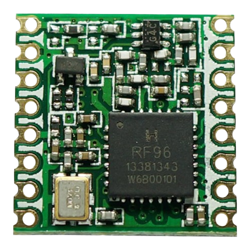
The RFM95 module is a compact, long-range transceiver featuring the LoRa (Long Range) spread spectrum modulation technology designed for high sensitivity and robust communication. It operates in the license-free 868/915 MHz ISM bands, making it suitable for a variety of applications in the Internet of Things (IoT), Machine to Machine (M2M) communication, and amateur radio uses.

Explore Projects Built with rfm95

Use Cirkit Designer to design, explore, and prototype these projects online. Some projects support real-time simulation. Click "Open Project" to start designing instantly!
Arduino UNO and RFM95 LoRa Transceiver with Inductor for Wireless Communication
Image of transmitter: A project utilizing rfm95 in a practical application
This circuit integrates an Arduino UNO with an RFM95 LoRa module for wireless communication. The Arduino provides power and control signals to the RFM95, while an inductor is connected to the antenna pin of the RFM95 to facilitate signal transmission. The setup is designed for applications requiring long-range, low-power wireless data transmission.
Cirkit Designer LogoOpen Project in Cirkit Designer
Arduino Nano-Based GPS Tracker with GSM and LoRa Communication
Image of Electromagnetic Sensor: A project utilizing rfm95 in a practical application
This circuit features an Arduino Nano microcontroller interfaced with an RFM95 LoRa transceiver module for long-range communication, a SIM800L GSM module for cellular connectivity, and a GPS NEO 6M module for location tracking. The Arduino Nano also connects to an inductive sensor for proximity or metal detection. The circuit is designed for applications requiring wireless communication, location tracking, and proximity sensing, with the Arduino Nano serving as the central processing unit.
Cirkit Designer LogoOpen Project in Cirkit Designer
Dual-Mode LoRa and GSM Communication Device with ESP32
Image of modul gateway: A project utilizing rfm95 in a practical application
This circuit features an ESP32 Devkit V1 microcontroller interfaced with an RFM95 LoRa transceiver module for long-range communication and a SIM800L GSM module for cellular connectivity. Two LM2596 step-down modules are used to regulate the 12V battery voltage down to 3.3V required by the ESP32, RFM95, and SIM800L. The ESP32 facilitates data exchange between the RFM95 and SIM800L, enabling the system to send/receive data over both LoRa and GSM networks.
Cirkit Designer LogoOpen Project in Cirkit Designer
ESP32 and RFM95 LoRa Transmitter with Inductor-Based Antenna
Image of transmitter LoRa: A project utilizing rfm95 in a practical application
This circuit is a LoRa transmitter system that uses an ESP32 microcontroller to communicate with an RFM95 LoRa module. The ESP32 initializes the LoRa module and sends periodic messages wirelessly, with an inductor connected to the antenna pin of the RFM95 for signal tuning.
Cirkit Designer LogoOpen Project in Cirkit Designer

Explore Projects Built with rfm95

Use Cirkit Designer to design, explore, and prototype these projects online. Some projects support real-time simulation. Click "Open Project" to start designing instantly!
Image of transmitter: A project utilizing rfm95 in a practical application
Arduino UNO and RFM95 LoRa Transceiver with Inductor for Wireless Communication
This circuit integrates an Arduino UNO with an RFM95 LoRa module for wireless communication. The Arduino provides power and control signals to the RFM95, while an inductor is connected to the antenna pin of the RFM95 to facilitate signal transmission. The setup is designed for applications requiring long-range, low-power wireless data transmission.
Cirkit Designer LogoOpen Project in Cirkit Designer
Image of Electromagnetic Sensor: A project utilizing rfm95 in a practical application
Arduino Nano-Based GPS Tracker with GSM and LoRa Communication
This circuit features an Arduino Nano microcontroller interfaced with an RFM95 LoRa transceiver module for long-range communication, a SIM800L GSM module for cellular connectivity, and a GPS NEO 6M module for location tracking. The Arduino Nano also connects to an inductive sensor for proximity or metal detection. The circuit is designed for applications requiring wireless communication, location tracking, and proximity sensing, with the Arduino Nano serving as the central processing unit.
Cirkit Designer LogoOpen Project in Cirkit Designer
Image of modul gateway: A project utilizing rfm95 in a practical application
Dual-Mode LoRa and GSM Communication Device with ESP32
This circuit features an ESP32 Devkit V1 microcontroller interfaced with an RFM95 LoRa transceiver module for long-range communication and a SIM800L GSM module for cellular connectivity. Two LM2596 step-down modules are used to regulate the 12V battery voltage down to 3.3V required by the ESP32, RFM95, and SIM800L. The ESP32 facilitates data exchange between the RFM95 and SIM800L, enabling the system to send/receive data over both LoRa and GSM networks.
Cirkit Designer LogoOpen Project in Cirkit Designer
Image of transmitter LoRa: A project utilizing rfm95 in a practical application
ESP32 and RFM95 LoRa Transmitter with Inductor-Based Antenna
This circuit is a LoRa transmitter system that uses an ESP32 microcontroller to communicate with an RFM95 LoRa module. The ESP32 initializes the LoRa module and sends periodic messages wirelessly, with an inductor connected to the antenna pin of the RFM95 for signal tuning.
Cirkit Designer LogoOpen Project in Cirkit Designer

Common Applications and Use Cases

  • Remote sensors and telemetry
  • Home and building automation
  • Wireless alarm and security systems
  • Industrial monitoring and control
  • Low-power wide-area networks (LPWAN)

Technical Specifications

Key Technical Details

  • Frequency Bands: 868 MHz (Europe) / 915 MHz (North America)
  • Modulation: LoRa Spread Spectrum
  • Output Power: +20 dBm - 100 mW constant RF output vs. V supply
  • Sensitivity: down to -148 dBm
  • Range: Up to 15 km (suburban), 2-5 km (urban environment)
  • Supply Voltage: 1.8 - 3.7 V
  • Operating Temperature: -40°C to +85°C

Pin Configuration and Descriptions

Pin Number Name Description
1 GND Ground connection
2 VCC Power supply (1.8 - 3.7 V)
3 DIO0 Digital I/O, configurable for interrupt and LoRa functions
4 DIO1 Digital I/O, configurable for interrupt and LoRa functions
5 DIO2 Digital I/O, configurable for interrupt and LoRa functions
6 DIO3 Digital I/O, configurable for interrupt and LoRa functions
7 DIO4 Digital I/O, configurable for interrupt and LoRa functions
8 DIO5 Digital I/O, configurable for interrupt and LoRa functions
9 RESET Reset pin (active low)
10 NSS SPI Chip Select (active low)
11 SCK SPI Clock
12 MOSI SPI Master Out Slave In
13 MISO SPI Master In Slave Out
14 GND Ground connection
15 ANT Antenna connection

Usage Instructions

How to Use the Component in a Circuit

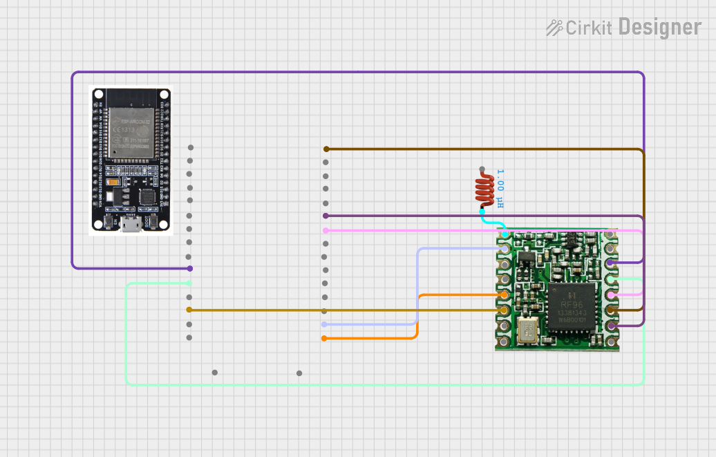
  1. Power Supply: Connect the VCC pin to a regulated 3.3V power source and the GND pin to the ground.
  2. SPI Interface: Connect the NSS, SCK, MOSI, and MISO pins to the corresponding SPI pins on your microcontroller.
  3. Interrupts: Optionally, connect DIO0-DIO5 to digital pins on your microcontroller for interrupt-driven events.
  4. Antenna: Attach an appropriate antenna to the ANT pin for signal transmission and reception.
  5. Reset: The RESET pin can be connected to a microcontroller pin for hardware reset functionality.

Important Considerations and Best Practices

  • Ensure that the power supply is clean and within the specified voltage range.
  • Use a 50-ohm impedance antenna suitable for the frequency band of operation.
  • Keep the RF path (from RFM95 to the antenna) as short as possible.
  • Follow local regulations regarding the transmission power and frequency usage.
  • Implement proper ESD precautions when handling the module.

Troubleshooting and FAQs

Common Issues Users Might Face

  • No Communication: Verify connections, ensure the correct frequency band is selected, and check that the antenna is properly connected.
  • Short Range: Check antenna placement and orientation, and ensure there are no obstructions or interference sources.
  • Intermittent Communication: Check for power supply stability and sufficient decoupling.

Solutions and Tips for Troubleshooting

  • Double-check solder joints and wiring for any loose connections.
  • Use a spectrum analyzer to verify the module is transmitting at the correct frequency.
  • Implement a proper ground plane on your PCB to improve performance.

FAQs

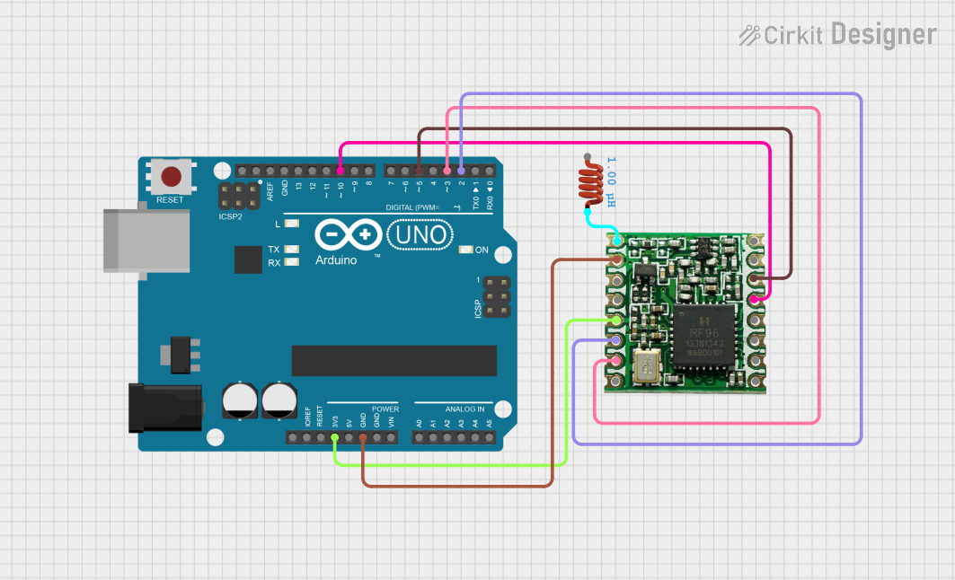
Q: Can I use the RFM95 module with an Arduino? A: Yes, the RFM95 can be interfaced with an Arduino using the SPI interface and appropriate libraries.

Q: What is the maximum range I can achieve with the RFM95? A: The range depends on the environment, antenna, and settings, but it can reach up to 15 km in open, suburban areas.

Q: Is the RFM95 module compatible with LoRaWAN? A: Yes, the RFM95 can be used in LoRaWAN networks with the correct firmware and network settings.

Example Arduino Code

Below is an example of how to initialize the RFM95 module with an Arduino UNO. This code assumes the use of the RadioHead library for LoRa communication.

#include <SPI.h>
#include <RH_RF95.h>

// Singleton instance of the radio driver
RH_RF95 rf95;

void setup() {
  Serial.begin(9600);
  while (!Serial) ; // Wait for serial port to be available
  if (!rf95.init()) {
    Serial.println("LoRa radio init failed");
    while (1);
  }
  Serial.println("LoRa radio init OK!");
  // Set frequency
  if (!rf95.setFrequency(915.0)) {
    Serial.println("setFrequency failed");
    while (1);
  }
  // Set the power level: 1-23, 23 being the highest
  rf95.setTxPower(23, false);
}

void loop() {
  // Send a message every 3 seconds
  const char *msg = "Hello World!";
  rf95.send((uint8_t *)msg, strlen(msg));
  rf95.waitPacketSent();
  delay(3000);
}

Remember to adjust the frequency and power level according to your regional regulations and requirements. The setFrequency function should be set to the appropriate frequency for your region (either 868 or 915 MHz).