How to Use IP5306 charging module: Examples, Pinouts, and Specs
Introduction
The IP5306 is a lithium battery charging and protection module designed to manage the charging and discharging of lithium-ion batteries efficiently. It integrates multiple safety features, including over-voltage, under-voltage, and over-current protection, ensuring the safe operation of connected devices. This module is widely used in portable electronic devices, power banks, and DIY battery-powered projects due to its compact size and robust functionality.
Explore Projects Built with IP5306 charging module


Explore Projects Built with IP5306 charging module
Common Applications
- Power banks and portable chargers
- DIY battery-powered projects
- Wearable devices
- IoT devices
- Small robotics and embedded systems
Technical Specifications
The IP5306 module is equipped with advanced features to ensure safe and efficient battery management. Below are its key technical specifications:
| Parameter | Value |
|---|---|
| Input Voltage Range | 4.5V to 6V |
| Output Voltage | 5V ± 0.2V |
| Charging Current | Up to 2.1A |
| Discharge Current | Up to 2.4A |
| Battery Overcharge Protection Voltage | 4.2V ± 0.05V |
| Battery Over-discharge Protection Voltage | 2.9V ± 0.1V |
| Efficiency (Boost Mode) | Up to 92% |
| Operating Temperature | -40°C to 85°C |
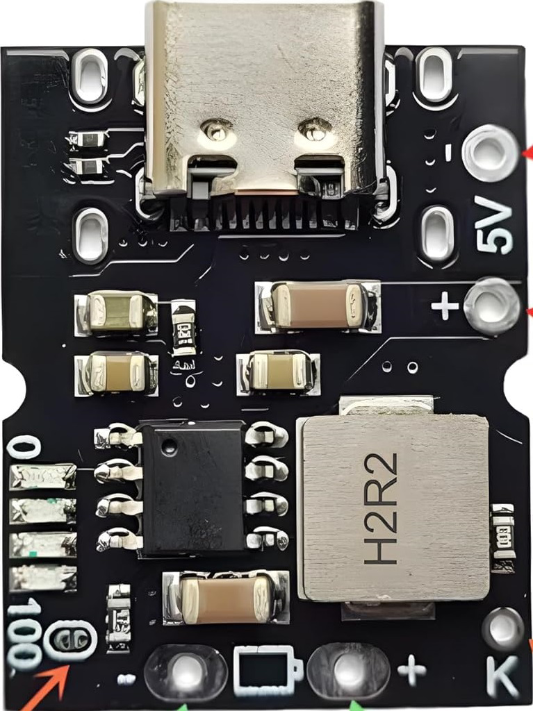
Pin Configuration and Descriptions
The IP5306 module typically comes with the following pinout:
| Pin Name | Description |
|---|---|
VIN |
Input voltage pin for charging (4.5V to 6V). Connect to a USB power source. |
GND |
Ground pin. Common ground for input, output, and battery. |
BAT+ |
Positive terminal for the lithium-ion battery. |
BAT- |
Negative terminal for the lithium-ion battery. |
5V OUT |
Regulated 5V output pin for powering external devices. |
KEY |
Control pin for enabling/disabling the output or toggling modes. |
LED1-LED4 |
Status indicator pins for battery level (commonly connected to onboard LEDs). |
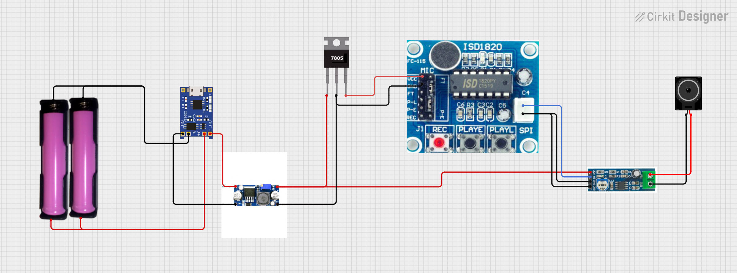
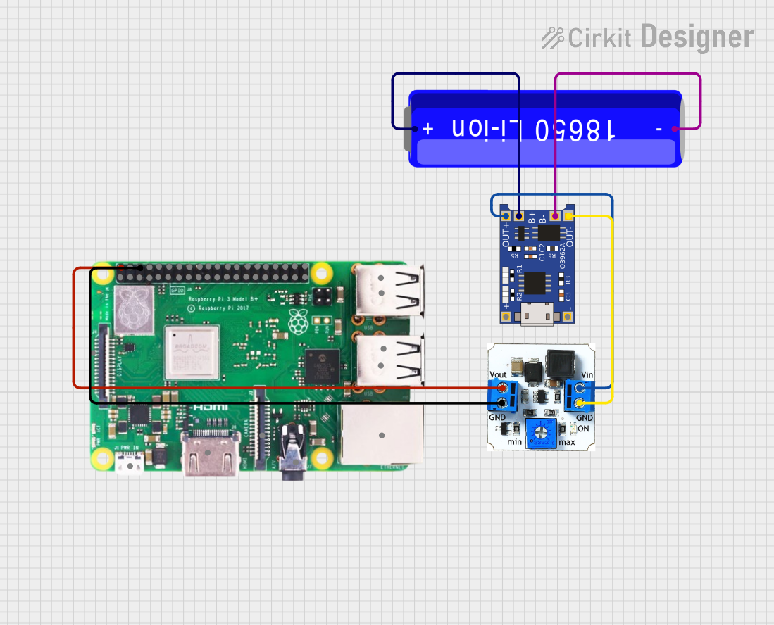
Usage Instructions
How to Use the IP5306 in a Circuit
- Connect the Battery: Attach the lithium-ion battery to the
BAT+andBAT-pins. Ensure correct polarity to avoid damage. - Provide Input Power: Connect a 5V USB power source to the
VINandGNDpins for charging the battery. - Output Power: Use the
5V OUTpin to power external devices. Ensure the connected load does not exceed the maximum discharge current (2.4A). - Monitor Battery Status: The onboard LEDs (or
LED1-LED4pins) indicate the battery charge level:- LED1: 0-25%
- LED2: 25-50%
- LED3: 50-75%
- LED4: 75-100%
- Control Output: Use the
KEYpin to toggle the output or enable/disable the module.
Important Considerations and Best Practices
- Battery Compatibility: Use only lithium-ion batteries with a nominal voltage of 3.7V and a maximum charge voltage of 4.2V.
- Heat Management: Ensure proper ventilation or heat dissipation if the module operates at high currents for extended periods.
- Avoid Overloading: Do not connect loads exceeding the maximum output current (2.4A) to prevent damage to the module.
- Polarity Protection: Double-check all connections to avoid reverse polarity, which can damage the module and battery.
Example: Using the IP5306 with an Arduino UNO
The IP5306 can be used to power an Arduino UNO via its 5V OUT pin. Below is an example of how to monitor the battery level using the Arduino:
// Example code to monitor battery level using IP5306 and Arduino UNO
// Connect the IP5306 LED pins (LED1-LED4) to Arduino digital pins 2-5.

#define LED1_PIN 2  // Pin connected to LED1 (0-25% battery level)
#define LED2_PIN 3  // Pin connected to LED2 (25-50% battery level)
#define LED3_PIN 4  // Pin connected to LED3 (50-75% battery level)
#define LED4_PIN 5  // Pin connected to LED4 (75-100% battery level)

void setup() {
  // Initialize serial communication for debugging
  Serial.begin(9600);

  // Set LED pins as input
  pinMode(LED1_PIN, INPUT);
  pinMode(LED2_PIN, INPUT);
  pinMode(LED3_PIN, INPUT);
  pinMode(LED4_PIN, INPUT);
}

void loop() {
  // Read the status of each LED pin
  bool led1 = digitalRead(LED1_PIN);
  bool led2 = digitalRead(LED2_PIN);
  bool led3 = digitalRead(LED3_PIN);
  bool led4 = digitalRead(LED4_PIN);

  // Determine battery level based on LED status
  if (led4) {
    Serial.println("Battery Level: 75-100%");
  } else if (led3) {
    Serial.println("Battery Level: 50-75%");
  } else if (led2) {
    Serial.println("Battery Level: 25-50%");
  } else if (led1) {
    Serial.println("Battery Level: 0-25%");
  } else {
    Serial.println("Battery Level: Unknown or No Battery");
  }

  // Wait for 1 second before checking again
  delay(1000);
}
Troubleshooting and FAQs
Common Issues and Solutions
Module Not Charging the Battery
- Cause: Incorrect input voltage or loose connections.
- Solution: Ensure the input voltage is between 4.5V and 6V. Check all connections.
No Output from the
5V OUTPin- Cause: Output is disabled or battery is discharged.
- Solution: Press the
KEYbutton to enable the output. Charge the battery if necessary.
Overheating During Operation
- Cause: High current draw or poor ventilation.
- Solution: Reduce the load or improve heat dissipation.
LED Indicators Not Working
- Cause: Faulty connections or damaged LEDs.
- Solution: Verify connections to the
LED1-LED4pins. Replace damaged LEDs if needed.
FAQs
Can I use the IP5306 with a 3.3V device?
- Yes, but you will need a voltage regulator or level shifter to step down the 5V output to 3.3V.
What happens if I connect a battery with a higher voltage?
- The module may get damaged. Always use a 3.7V lithium-ion battery with a maximum charge voltage of 4.2V.
Can I charge and discharge the battery simultaneously?
- Yes, the IP5306 supports pass-through charging, allowing you to charge the battery while powering a load.
How do I reset the module?
- Disconnect the input power and battery, then reconnect them to reset the module.