How to Use ESP32s3: Examples, Pinouts, and Specs
Introduction
The ESP32-S3, manufactured by ESP, is a powerful and versatile system on a chip (SoC) designed for Internet of Things (IoT) applications. It combines integrated Wi-Fi and Bluetooth Low Energy (BLE) capabilities with a dual-core processor, making it suitable for a wide range of smart devices and wireless connectivity solutions. The ESP32-S3 is optimized for low power consumption, making it ideal for battery-powered devices.
Explore Projects Built with ESP32s3


Explore Projects Built with ESP32s3
Common Applications and Use Cases
- Smart home devices (e.g., smart lights, thermostats, and security systems)
- Wearable technology
- Industrial IoT applications
- Wireless sensor networks
- Robotics and automation
- Audio streaming and voice recognition systems
- Edge computing and AI/ML applications
Technical Specifications
The ESP32-S3 offers a robust set of features and specifications to meet the demands of modern IoT applications.
Key Technical Details
| Specification | Value |
|---|---|
| Manufacturer | ESP |
| Part ID | ESP |
| Processor | Dual-core Xtensa® LX7 @ up to 240 MHz |
| Wireless Connectivity | Wi-Fi 802.11 b/g/n (2.4 GHz), BLE 5.0 |
| Flash Memory | Up to 16 MB |
| SRAM | Up to 512 KB |
| GPIO Pins | 45 (configurable for various functions) |
| Operating Voltage | 3.0V to 3.6V |
| Power Consumption (Idle) | ~10 µA (deep sleep mode) |
| Peripherals | SPI, I2C, I2S, UART, ADC, DAC, PWM, etc. |
| AI Acceleration | Vector instructions for AI/ML workloads |
| Operating Temperature Range | -40°C to +85°C |
| Package | QFN48 |
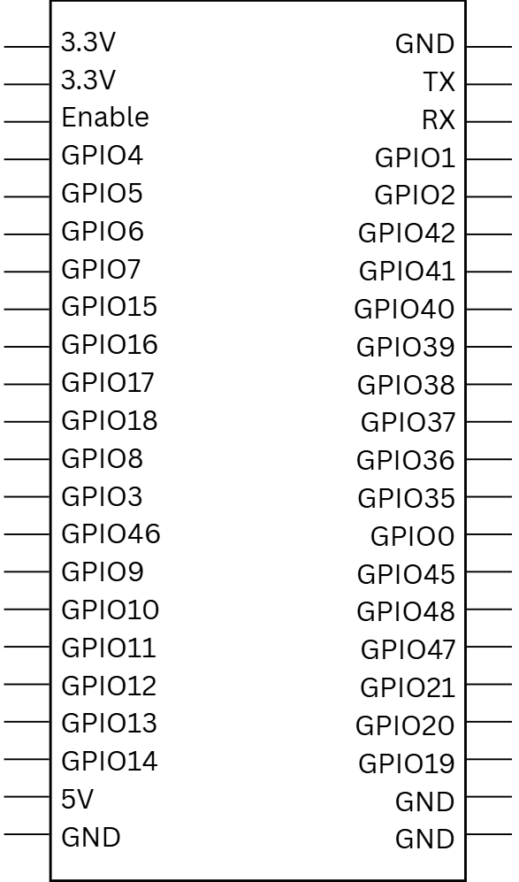
Pin Configuration and Descriptions
The ESP32-S3 has a flexible pinout that supports multiple functions. Below is a table of commonly used pins and their descriptions:
| Pin Number | Pin Name | Functionality |
|---|---|---|
| 1 | GPIO0 | General-purpose I/O, boot mode selection |
| 2 | GPIO1 | General-purpose I/O, UART TX |
| 3 | GPIO2 | General-purpose I/O, ADC, PWM |
| 4 | GPIO3 | General-purpose I/O, UART RX |
| 5 | GPIO4 | General-purpose I/O, ADC, PWM |
| 6 | GPIO5 | General-purpose I/O, SPI CS |
| 7 | GPIO6 | General-purpose I/O, SPI CLK |
| 8 | GPIO7 | General-purpose I/O, SPI MOSI |
| 9 | GPIO8 | General-purpose I/O, SPI MISO |
| ... | ... | ... |
Note: The ESP32-S3 supports multiplexing, allowing most pins to serve multiple functions. Refer to the official datasheet for a complete pinout.
Usage Instructions
The ESP32-S3 is highly versatile and can be used in a variety of circuits. Below are the steps and best practices for using the ESP32-S3 in your projects.
How to Use the ESP32-S3 in a Circuit
Power Supply:
- Provide a stable 3.3V power supply to the ESP32-S3. Avoid exceeding 3.6V to prevent damage.
- Use decoupling capacitors (e.g., 0.1 µF and 10 µF) near the power pins to reduce noise.
Boot Mode Selection:
- Connect GPIO0 to GND during power-up to enter bootloader mode for programming.
- For normal operation, ensure GPIO0 is pulled high.
Programming:
- Use a USB-to-UART bridge (e.g., CP2102 or FTDI) to connect the ESP32-S3 to your computer.
- Flash firmware using the ESP-IDF (Espressif IoT Development Framework) or Arduino IDE.
Peripherals:
- Connect sensors, actuators, or other peripherals to the GPIO pins.
- Configure the pins in your code to match the required functionality (e.g., SPI, I2C, PWM).
Important Considerations and Best Practices
- Wi-Fi and BLE Antenna: Ensure the onboard antenna has sufficient clearance from metal objects to avoid signal interference.
- Deep Sleep Mode: Use deep sleep mode to minimize power consumption in battery-powered applications.
- GPIO Voltage Levels: The GPIO pins are not 5V-tolerant. Use level shifters if interfacing with 5V devices.
- Firmware Updates: Regularly update the firmware to benefit from the latest features and security patches.
Example Code for Arduino IDE
Below is an example of how to use the ESP32-S3 with the Arduino IDE to blink an LED connected to GPIO2:
// Define the GPIO pin for the LED
#define LED_PIN 2

void setup() {
  // Initialize the LED pin as an output
  pinMode(LED_PIN, OUTPUT);
}

void loop() {
  // Turn the LED on
  digitalWrite(LED_PIN, HIGH);
  delay(1000); // Wait for 1 second

  // Turn the LED off
  digitalWrite(LED_PIN, LOW);
  delay(1000); // Wait for 1 second
}
Tip: Install the ESP32 board package in the Arduino IDE before uploading the code. Go to
File > Preferences, add the ESP32 board URL, and install the package via the Board Manager.
Troubleshooting and FAQs
Common Issues and Solutions
ESP32-S3 Not Detected by Computer:
- Ensure the USB cable is functional and supports data transfer.
- Install the correct USB-to-UART driver for your operating system.
Wi-Fi Connection Fails:
- Verify the SSID and password in your code.
- Check for interference or weak signal strength.
GPIO Pin Not Working:
- Confirm the pin is not being used for another function (e.g., boot mode).
- Check for short circuits or incorrect wiring.
High Power Consumption:
- Ensure the ESP32-S3 is entering deep sleep mode when idle.
- Disable unused peripherals in your code.
FAQs
Q: Can the ESP32-S3 be powered by a 5V source?
A: No, the ESP32-S3 operates at 3.3V. Use a voltage regulator or level shifter if interfacing with 5V systems.
Q: How do I reset the ESP32-S3?
A: Press the onboard reset button or toggle the EN (enable) pin.
Q: Does the ESP32-S3 support over-the-air (OTA) updates?
A: Yes, the ESP32-S3 supports OTA updates, allowing you to update firmware wirelessly.
Q: Can I use the ESP32-S3 for AI/ML applications?
A: Yes, the ESP32-S3 includes vector instructions optimized for AI/ML workloads, making it suitable for lightweight AI tasks.
For additional support, refer to the official ESP32-S3 datasheet and Espressif's documentation.